13
2.0 System Use
2.1
FALL PROTECTION AND RESCUE PLAN:
The employer must have a Fall Protection and Rescue Plan. The plan should
provide guidelines and requirements for an employer’s managed fall protection program, including policies, duties and
training; fall protection procedures; eliminating and controlling fall hazards; rescue procedures; incident investigations;
and evaluating program effectiveness.
2.2
INSPECTION FREQUENCY:
SRDs shall be inspected by the authorized person
1
or rescuer
2
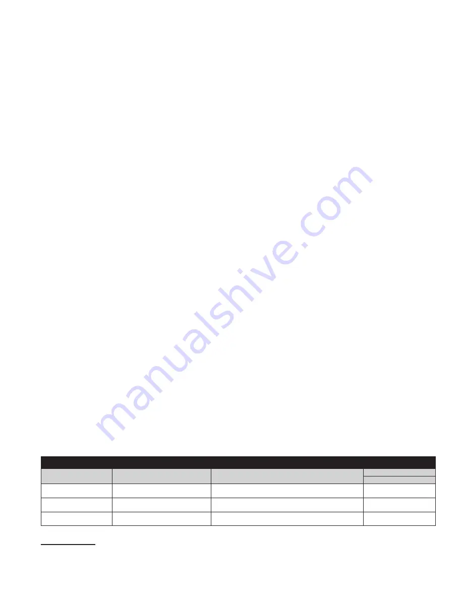
before each use (See Table
3). Additionally, inspections shall be conducted by a competent person
3
other than the user. Extreme working conditions
(harsh environment, prolonged use, etc.) may necessitate more frequent competent person inspections. The competent
person shall use the
Inspection Schedule (Table 2)
to determine appropriate inspection intervals. Inspection procedures
are described in the
Inspection & Maintenance Log (Table 3)
. Results of the Competent Person inspection should be recorded
in the
Inspection and Maintenance Log
or recorded with the Radio Frequency Identification (RFID) system.
2.3
NORMAL OPERATIONS:
Normal operation will allow the lifeline to extend and retract with no hesitation or slack as
the worker moves at normal speeds. If a fall occurs, a speed sensing brake system will activate, stopping the fall and
absorbing much of the energy created. Sudden or quick movements should be avoided during normal work operation, as
this may cause the SRD to lock up. For falls which occur near the end of the lifeline travel, a reserve lifeline system or
Energy Absorber has been incorporated to reduce the fall arrest forces.
2.4
BODY SUPPORT:
A Full Body Harness must be used with the Self-Retracting Device. The harness connection point must be
above the user’s center of gravity. A body belt is not authorized for use with the Self-Retracting Device. If a fall occurs when
using a body belt it may cause unintentional release or physical trauma from improper body support.
2.5
COMPATIBILITY OF COMPONENTS:
Unless otherwise noted, 3M equipment is designed for use with 3M approved
components and subsystems only. Substitutions or replacements made with non approved components or subsystems may
jeopardize compatibility of equipment and may affect safety and reliability of the complete system.
2.6
COMPATIBILITY OF CONNECTORS:
Connectors are considered to be compatible with connecting elements when they
have been designed to work together in such a way that their sizes and shapes do not cause their gate mechanisms to
inadvertently open regardless of how they become oriented. Contact 3M if you have any questions about compatibility.
Connectors (hooks, carabiners, and D-rings) must be capable of supporting at least 22.2 kN (5,000 lbs). Connectors
must be compatible with the anchorage or other system components. Do not use equipment that is not compatible.
Non-compatible connectors may unintentionally disengage (see Figure 5). Connectors must be compatible in size, shape,
and strength. Self-locking snap hooks and carabiners are required. If the connecting element to which a snap hook or
carabiner attaches is undersized or irregular in shape, a situation could occur where the connecting element applies a
force to the gate of the snap hook or carabiner (A). This force may cause the gate to open (B), allowing the snap hook or
carabiner to disengage from the connecting point (C).
2.7
MAKING CONNECTIONS:
Snap hooks and carabiners used with this equipment must be self-locking. Ensure all
connections are compatible in size, shape and strength. Do not use equipment that is not compatible. Ensure all
connectors are fully closed and locked. 3M connectors (snap hooks and carabiners) are designed to be used only as
specified in each product’s user’s instructions. See Figure 6 for examples of inappropriate connections.
Do not connect snap hooks and carabiners
:
A. To a D-ring to which another connector is attached.
B. In a manner that would result in a load on the gate. Large throat snap hooks should not be connected to standard
size D-rings or similar objects which will result in a load on the gate if the hook or D-ring twists or rotates, unless the
snap hook is equipped with a 16 kN (3,600 lb) gate.
C.
In a false engagement, where size or shape of the mating connectors are not compatible and, without visual
confirmation, the connectors seem fully engaged.
D. To each other.
E. Directly to webbing or rope lanyard or tie-back (unless the manufacturer’s instructions for both the lanyard and
connector specifically allows such a connection).
F. To any object which is shaped or dimensioned such that the snap hook or carabiner will not close and lock, or that
roll-out could occur.
G. In a manner that does not allow the connector to align properly while under load.
Table 2 – Inspection Schedule
Type of Use
Application Examples
Conditions of Use
Inspection Frequency
Competent Person
Infrequent to Light
Rescue and Confined Space,
Factory Maintenance
Good Storage Conditions, Indoor or Infrequent
Outdoor Use, Room Temperature, Clean Environments
Annually
Moderate to Heavy
Transportation, Residential
Construction, Utilities, Warehouse
Fair Storage Conditions, Indoor and Extended Outdoor
Use, All Temperatures, Clean or Dusty Environments
Semi-Annually to
Annually
Severe to Continuous
Commercial Construction, Oil and
Gas, Mining
Harsh Storage Conditions, Prolonged or Continuous
Outdoor Use, All Temperatures, Dirty Environment
Quarterly to Semi-
Annually
1 Authorized Person:
A person assigned by the employer to perform duties at a location where the person will be exposed to a fall hazard.
2 Rescuer:
Person or persons other than the rescue subject acting to perform an assisted rescue by operation of a rescue system.
3 Competent Person:
An individual designated by the employer to be responsible for the immediate supervision, implementation, and monitoring of the employer’s
managed fall protection program who, through training and knowledge, is capable of identifying, evaluating, and addressing existing and potential fall hazards, and
who has the employer’s authority to take prompt corrective action with regard to such hazards.
Summary of Contents for DBI-SALA Nano-Lok 3101521
Page 2: ......
Page 3: ...3 2 A C B E D E D A C B D F A C B F D D A A B B C C 3 A B FC FF DD SF FC FF DD SF C FC H ...
Page 4: ...4 4 x 1 140 kg V H FC V 1 2 m H 1 2 m FC 5 0 m V H FC x 1 140 kg 5 6 A B C A B C D E G 7 ...
Page 5: ...5 8 9 1 B A B A Delta III ExoFit NEX 2 C C D 3 E A C 4 F D D ...
Page 6: ...6 10 1 A B B A Delta III ExoFit NEX 2 D D C E 3 G H F 4 F A 5 F E I G E 6 D D C A D D K K C J ...
Page 7: ...7 11 1 A B 2 C D D 3 E G F 4 A E 5 E F 6 D C A ...
Page 8: ...8 12 E D A D G B F C F 13 14 A B C 15 ...
Page 9: ...9 16 17 18 19 C D B B A A E E A B C D A B 20 A B A B C E D C D 7 10 4 5 6 E 1 2 3 8 9 11 ...
Page 174: ......
Page 175: ......


