background image

Summary of Contents for Dynatel 500

Page 1: ......

Page 2: ......

Page 3: ...or Identification 14 II APPLICATIONS 2 1 Locating Slack Loops and Butt Splices 16 2 2 Locating Unknown Laterals 17 2 3 Locating Cables from Pedestals or Accessible Closures 17 2 4 Service Drop Path Lo...

Page 4: ......

Page 5: ......

Page 6: ...n I OPERATION CABLE AND ACCESSORY STORAGE WELL EXTERNAL INPUT AND HEADPHONE OUTPUT JACKS TRANSMITTER OUTPUT JACK A Transmitter Unit b Receiver Unit Figure 1 Dynatel Model 500 Cable Locator IV DYNATEL...

Page 7: ...r setup and no connections are required for the receiver which can be operated with one hand at normal walking speeds ERATION The tone receiver is a very sensitive tuned unit that receives only the si...

Page 8: ...th the BATtery test position of the TRANSMITTER output selector above See Section 3 for battery test procedures 2 1 3 RECEIVER CONTROLS The Receiver controls are shown in Fig 3 and described below See...

Page 9: ...Section I OPERATION o Q in Q DYNATEL CABLE LOCATOR BAT TEST OUTPUT OFF NORMAL TRANSMITTER Figure 2 Transmitter Controls See Section 1 2 DYNATEL m...

Page 10: ...c The Volume Control Knob controls the meter sensitivity loudness of tone from the receiver loudspeaker and the head phone output level at the headphone jack d The Loudspeaker provides an audible tone...

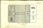
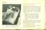
Page 11: ...Section I OPERATION Figure 3 Receiver Controls See Section 1 3 DYNATEL jJ Jj fjj 5...

Page 12: ...onnection if other cables or pipes are in the same area DYNA COUPLER If access to the cable is available this is the easiest and most accurate way to put tone on only one cable Connect the coupler ass...

Page 13: ...n the ground If the trans mitter cannot be placed on the ground then connect the black clip to ground This completes DYNATEL j jj jjj jj Section 1 OPERATION the transmitter setup instructions See Sect...

Page 14: ...e controls both the loudspeaker volume and the meter sensitivity Cable location accuracy is increased by turning up the volume control this also increases the meter sensitivity As the volume control i...

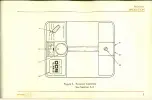
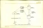
Page 15: ...Section I OPERATION Figure 5 Cable Location for Peak Null Modes DYNATELg 9...

Page 16: ...l receiver sensitivity Note When using the receiver in PEAK mode be sure that the handle is PARALLEL to the cable run If you turn the handle so that it is ACROSS the cable run the receiver output will...

Page 17: ...d See Fig 7 6 To locate the depth of underground cable in a duct be sure to subtract the diameter of the duct from the depth of the cable This helps prevent damage to the duct The above cable depth lo...

Page 18: ...MODE TO SET ADJUST THE VOLUME CONTROL SO THE METER INDICATES SET 2 THEN THIS SET RECEIVER MODE TO PEAK LIFT RECEIVER UNTIL METER NEEDLE RETURNS TO SET T 77777777777777777777777777777777777 GROUND DIS...

Page 19: ...Y OVER CABLE V777777777777777777 GROUND CABLE 2 THEN THIS RECEIVER NULL WHEN HELD 45 FOR BEST ACCURACY HOLD CLOSE TO GROUND 1ST MARK 77d 77777777777777 I CABLE V777777777777777777777 2ND MARK DISTANCE...

Page 20: ...tone Use the following procedure 1 Put the tone on the cable Use either a Dyna Coupler or make a direct con nection See Section 1 4 14 Notes a If a Dyna Coupler is used to put the tone on the cable t...

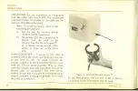
Page 21: ...Section I OPERATION Figure 9 Receiver Setup for Cable Identificatio DYNATEL 15...

Page 22: ...the tone from the receiver will increase and the meter needle will go to the right This indicates a sudden curve in the cable path and it could be a butt splice or a loop Note The receiver can sense l...

Page 23: ...FROM PEDESTALS OR ACCESSIBLE CLOSURES To locate cables or service drops coming out of DYNATEtgKjj Section II APPLICATIONS ready access closures or pedestals use the Dyna Coupler to put tone on the one...

Page 24: ...Section II APPLICATIONS 1 MARK SPLICE WITH LATERAL Figure 1 1 Locating Laterals Drops from Splice Encapsulation Riser etc 18 DYNATEL D 1...

Page 25: ...und If the cable is clear at both ends the direct connection is suggested Set the DYNATEL t j Hjljj Section II APPLICATIONS receiver in PEAK mode and follow the cable path until the tone suddenly decr...

Page 26: ...ern cells See Table A for replace ment types To change the transmitter batteries use the following procedure 1 For access to the transmitter battery com 20 RATION REPLACEMENT partment take the receive...

Page 27: ...ay and fasten is Table A Cable Locator Replacement Batteries Unit Voltage NEDA Eveready Burgess Transmitter 6V 915 51 OS F4BP Receiver 9V 1602 246 2N6 rfi s Each unit requires two batteries Figure 12...

Page 28: ...nsmitter All batteries are disconnected when the receiver is placed in the transmitter case To use the locator or to check the batteries remove the receiver 22 TRANSMITTER The Transmitter battery life...

Page 29: ...strument for service or repair be sure to include the following information a Name and address of owner b Brief discussion of symptoms or trouble RVICE INFORMATION c If possible send the name and tele...

Page 30: ......

Page 31: ...9...

Page 32: ...Dynatel Department TelComm Products Division 3M 380 N Pastoria Avenue Post Office Box 60549 Sunnyvale California 94088 USA Telephone 408 733 4300 TWX 910 339 9202...

Reviews: