background image

Operation

Section 1

Page 42

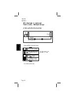
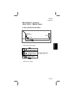
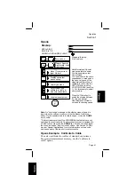
For this example, connect the leads
to the Cable Self Test Circuit (shown
here) RED to R and BLACK to B
only.

R

B

G

Y

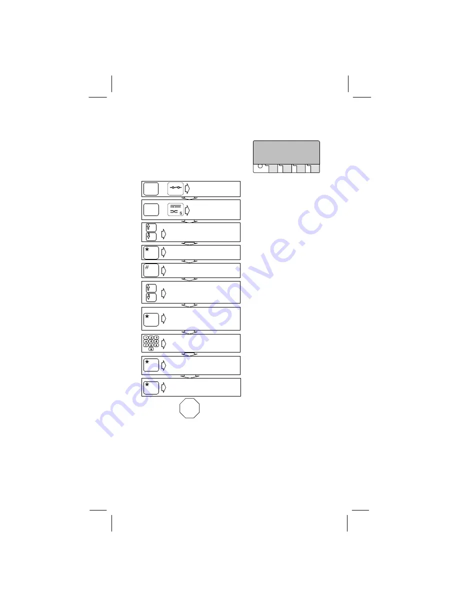
Turn unit on.

Both Normal and Special
modes operate the same.
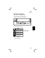
For this example, select
Normal mode.

Normal, Special,
Split Locate, Load
Coil Count

Enter reference pair
length: 440 ft/43 m

Move

 ✽ 

to select test

type– Normal

Display shows last
opens set-up

Cable type menu

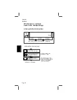
Select cable type,
calibrate to cable, or
measure capacitance

Connect red, black clips
to pair of known length,
green to shield

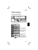
Calibration results for
tip, ring and mutual

Length measurement
results.

Disregard this step if the unit
is on.

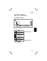
For this example, select
calibrate to cable.

Use arrow keys to move
cursor.

End

of

Test

The results are now stored
under the “Use Calibration”
option in the cable type
menu. Press the

 ✽ 

(star key)

to switch the display between
tip, ring and mutual. Mutual is
not used for locating opens.

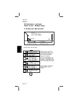
Record these results for
custom cable programming
in the Auto-Cal function.

For this example, connect
the red and black leads only
to the Cable Self Test Circuit
(see above).

On

Reset

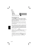
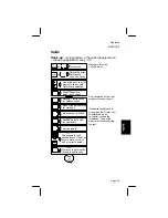
Opens

OR

OR

Summary of Contents for Dynatel 900 Series

Page 1: ...900M Series Test Set Operators Manual September 1996 78 8093 0453 4 Revision D Advanced Test Equipment Rentals www atecorp com 800 404 ATEC 2832 Established 1981 3M Dynatel 965 Specs Provided by www...

Page 2: ...Series Test Sets Operators Manual The information in this manual is proprietary to 3M and may not be reprinted or otherwise copied without the express written permission of 3M 1996 Minnesota Mining Ma...

Page 3: ...6 G Other Setups 7 4 DIAL 8 DC Line Test 10 Voltage 12 Current 14 Ohms 16 Ohms to Distance Ohms Ft 18 Resistance Fault Locate 20 Tone 38 Opens 40 Splits 44 AC Line Test 48 Ringers 50 REG 52 Loss 54 N...

Page 4: ...965M SUBSCRIBER LOOP ANALYZER 72 A Measurements 72 B Resistance Fault Locate 73 C Outputs 75 D Environment 75 E Dimensions 75 F Battery Power 75 Section Four Care and Maintenance 1 TEST LEAD AND BATTE...

Page 5: ...ding but not limited to some organizational changes to aid in use of this manual Comments concerning the contents or organization of this document as well as suggestions for improvement are welcomed D...

Page 6: ...th operating instructions for each function Instructions include descriptions of each test hookup instructions and a step by step example of each test function Section Two Special Applications contain...

Page 7: ...Gauge A numerical table designating the cross sectional area of wire The larger the AWG number the smaller the wire Balance The amount of current cancellation along tip and ring conductors The subscri...

Page 8: ...arameter such as power or voltage often used in measuring loss or gain of power in a device or circuit DLL Dial Long Line a loop treatment device to boost the loop current Dial Pulse The method of tel...

Page 9: ...in mA required to operate C O equipment and station apparatus at the subscriber premises Loop Treatment REG DLL etc This is C O extension equipment placed on a pair to overcome excessive line loss Lo...

Page 10: ...sured in dBrnC REG Range Extender with Gain loop treatment boosts C O battery voltage and amplifies AC speech signal Ringers The ringer circuit of a subscriber telephone set wired tip wired ring or br...

Page 11: ...ir diagnostic testing and resistance fault locating as well as opens and splits test functions and load coil counting The 945 and 945M Subscriber Loop Testers combine the 955 955M functions except res...

Page 12: ...mple some can read up to 3 Mohms while others can read up to 30 Mohms In comparison the digital 900 900M Series unit can read high resistance faults up to 100 Mohms 1 4 With an analog meter you have t...

Page 13: ...alog Reading 3 Megohms SHORT High Resistance Comparative Displays of Digital and Analog Readings of a Faulted Pair 900 900M Series Test Set Display Digital Reading 1 5 Other analog meters have convert...

Page 14: ...d step by step flowcharts of each test function Notes on Using the Test Set 2 2 DISPLAY Adjust display visibility by pressing up arrow key or down arrow key when the unit is first turned on If your se...

Page 15: ...hen press the star key to activate the function A Charge Battery 3 2 For rechargeable batteries only use this option and follow the displayed instructions to use the internal battery charger The unit...

Page 16: ...s the Reset key to continue D Battery Type 3 5 To control charging the unit must know what type batteries it contains Select this function then press either the star key for rechargeable nickel cadmiu...

Page 17: ...her Setups 3 10 Use this option to control the sound of the keystroke beeps For the 900 T series test sets use this option to setup the real time clock and view the log which shows information about t...

Page 18: ...row keys to move cursor use key pad to enter number Disregard this step if the unit is on Dial type menu Turn unit on Unit monitors line End of Test Press for ground start otherwise press Unit dials n...

Page 19: ...caller I D End of Test On Reset DIAL Unit monitors line displays caller I D You can press the key to go to number dialing Received data displayed in hexadecimal format The data displayed includes seiz...

Page 20: ...placed into service or any pair with suspected problems Attach the leads then turn the unit on Always verify results with appropriate manual tests blue keys before taking corrective action Caution If...

Page 21: ...vailable in 945 945M 2 Not available in 955 955M DC LINE TEST EXTENDERS VOLTAGE OHMS GROUND CABLE TYPE CURRENT OPENS DIAL TONE FAULT YES NO STATIC YES NO RINGERS END of TEST Note On some floating tip...

Page 22: ...nually Note Voltage accuracy can be affected when source impedance exceeds the 900 900M Series Test Set input impedance of 1 11 Megohms The user can compute the true voltage reading considering the 1...

Page 23: ...gurations by pressing the and keys Disregard this step if the unit is on Show ring ground VDC results Show ring ground VAC results Turn unit on Run test show tip ring VDC results End of Test Show tip...

Page 24: ...nction also tests ground resistance to check integrity of the ground connection at the station protector Press the CURRENT key and the unit applies a 430 ohm short across the pair to simulate an off h...

Page 25: ...965M units only you can press the pound key to switch the display from loop current to station ground resistance and back Disregard this step if the unit is on Note On some floating tip switches such...

Page 26: ...C O battery level or dirty test clips keep them clean A rising or falling tone indicates large resistance fluctuations Use the OHMS key to test the good and faulty conductors before using the RESISTA...

Page 27: ...ground resistance You can press the ohms to distance key to convert the resistance measurement to distance or press any other test key to exit this test program Disregard this step if the unit is on...

Page 28: ...ion You can also use the keypad to enter the value to be converted Remember this function is a calculator it does not replace the resistance fault locate measurements Caution If hazardous voltage warn...

Page 29: ...ter amount to be converted Select wire gauge Use arrow keys to move cursor to wire gauge size Select temperature Use arrow keys to move cursor use keypad to enter temperature Select ohms to distance d...

Page 30: ...er retrieval in the terminal mode for more information see the Terminal Emulation manual for your unit A detailed setups chart and examples follow the RFL flowchart There are four major set ups a Unit...

Page 31: ...ce to strap DTF Distance to fault STF Distance strap to fault On Reset This is the last used setup start here if coming from RFL setups on page 22 If the unit tells you to move closer to the fault mov...

Page 32: ...CHANGE SETUPS TURN SET ON PRESS RES FLT LOCATE KEY SETUPS DISPLAY USE SETUPS MEASURE DTS OHMS USE DEFAULT FEET SINGLE GAUGE CHECK SECTIONS MULTIPLE GAUGE CONTINUE SELECT HOOKUP CHECK SECTIONS GAUGE L...

Page 33: ...Good 1 Good 2 Common end to faulted ring Strap End 2 to Good 2 Strap End 1 to Good 1 Straps at Far End Separate Good Pair for ground or battery cross Black to reference in this case to ground Red to...

Page 34: ...red Disregard this step if the unit is on For this example use 19 AWG or 912 mm The numbers displayed may vary due to variations in the resistors in the Cable Self Test Circuit See page 85 for limits...

Page 35: ...arrow keys to line up with 19 AWG or 912 mm DTS known Select gauge Disregard this step if the unit is on Always check the setups Press the star key to use the stored setups if they are correct contin...

Page 36: ...an press the pound key to repeat the test Display computed temperature Additional message if any End of Test Continue hookup as instructed You can press the pound key to repeat the temperature calcula...

Page 37: ...on Stored setups Change setups Temperature Use arrow keys to move cursor to multiple gauge Press the star key to use the stored setups if they are correct continued on next page Gauge selection Numbe...

Page 38: ...for the first section Strap Test Set 205 ft or 63 m 26 AWG or 4 mm Pick section 1 gauge Use arrow keys to line up with 26 AWG or 4mm continued on next page For this example use 26 AWG or 4 mm Use key...

Page 39: ...on 1179 ft or 359 m 24 AWG or 5 mm Strap Test Set 205 ft or 63 m 26 AWG or 4 mm Use arrow keys to line up with 24 AWG or 5 mm Length of section 2 For this example use 24 AWG or 5 mm Use keypad to ente...

Page 40: ...nknown 1179 ft or 359 m 24 AWG or 5 mm 205 ft or 63 m 26 AWG or 4 mm Pick section 3 gauge Use arrow keys to line up with 22 AWG or 7 mm Length of section 3 unknown On multiple gauge fault locate one s...

Page 41: ...straps hookup instruction Stored setups continue with test Continue test Select hookup separate good pair End of Test In the field use the arrow keys here to view the rest of the instructions and con...

Page 42: ...1 C 2 sections House Protector Strap Turn unit on Stored setups Change setups DTS known Display units in feet or meters Gauge select menu Use arrow keys to select multiple gauge Number of sections in...

Page 43: ...auge 2 Set up for the first section unknown Test Set House Protector 24 AWG or 511 mm Strap Pick section 1 gauge Use arrow keys to line up with 24 AWG or 511 mm Section 1 length unknown continued on n...

Page 44: ...xt section 26 AWG or 4 mm unknown unknown Test Set House Protector 24 AWG or 511 mm Strap Continue test Length of section 2 unknown Use arrow keys to line up with 26 AWG or 4 mm Pick section 2 gauge w...

Page 45: ...ctor 24 AWG or 511 mm Strap Stored setups splice locate Cable temperature Enter DTS distance to straps Select hookup separate good pair Use arrow keys to move cursor use keypad to enter DTS 2500 ft or...

Page 46: ...alculated Splice Sec 1 330 ft 114 m Sec 2 2121 ft 648 m DTS 2500 ft 762 m DTF 360 ft 115 m STF 2140 ft 647 m DTS 2500 ft 762 m Sec 2 Do Fault Locate End of Test In this example the display shows that...

Page 47: ...the good conductor being the same length gauge and preferably in the same pair or cable group For example if the good conductor is shorter than the faulted conductor or is a larger wire diameter than...

Page 48: ...pair identification The unit can send tone for two hours before automatic shut off With the TONE key you can apply precision tone to the cable for loss measurements With the 965 965M you can also appl...

Page 49: ...lete loops and loops less than 500 ohms Soft tone indicates loops of greater than 500 ohms If you choose an ID tone you can choose to send interrupted tone by pressing the star key or continuous tone...

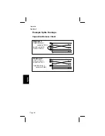
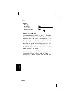
Page 50: ...The test set has two Opens functions normal and special Use the special mode on cables shorter than 10 000 feet for opens with resistance faults crossed battery or high noise The special mode does no...

Page 51: ...cable profiles or calibrate to cable Use the AUTO CAL key to set up CUSTOM CABLE see Sec 1 For this example select aircore cable OR OR Note An overrange message on the display means the pair is longer...

Page 52: ...capacitance Connect red black clips to pair of known length green to shield Calibration results for tip ring and mutual Length measurement results Disregard this step if the unit is on For this exampl...

Page 53: ...m 1 Early software versions of the 900 900M Series test sets are not equipped to count load coils To determine if your set is equipped to do load coil counts press the OPENS key If the set is so equi...

Page 54: ...ferent location excessive crosstalk may result To correct the original split and the correcting split use the far end to split measurement to get the distance between the splits Then get between the t...

Page 55: ...arrow keys to scroll display to line up with Split Locate selection Distance to split results farend to split results Check capacitive balance or bypass Hookup 1 instructions for balance check Balanc...

Page 56: ...its Hookups Capacitive Balance Check Pair 3 Hookup 1 GREEN to PAIR 1 shorted to PAIR 3 BLACK to SPLIT 2 RED to GOOD 2 Pair 1 Pair 2 B R G Hookup 2 RED to GOOD 1 BLACK to SPLIT 1 GREEN to PAIR 2 shorte...

Page 57: ...Operation Section 1 Page 47 Split Locate Hookup Hookup RED to GOOD 1 BLACK to SPLIT 1 GREEN to SPLIT 2 YELLOW to GOOD 2 shorted to PAIR 3 Pair 3 Pair 1 Pair 2 R B G Y...

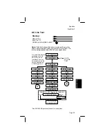
Page 58: ...ctive action To be sure you can dial to the farend test lines learn about the unit s LOSS and NOISE functions found in this section of the manual before running AC LINE TEST Attach the leads as shown...

Page 59: ...ROUND See 3M 1020B Operators Manual for instructions AC LINE TEST VOLTAGE CURRENT LOSS NOISE PWR INFLUENCE BALANCE DIAGNOSIS END OF TEST 3M 1020 MILLIWATT STEP TONE LOSS LOSS NOISE COMMAND SLOPE DIAGN...

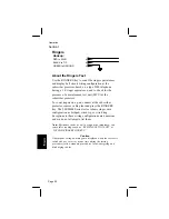
Page 60: ...pair connect at the subscriber protector remove cable plant and press the RINGERS key The 900 900M Series test set shows ringer wire configuration as bridged wired tip or wired ring Exceptions to the...

Page 61: ...this step if the unit is on End of Test PLEASE WAIT until the results appear Results ringer count and wiring configuration Use arrow keys to move cursor to line up with Ringer selection Ringer Ringer...

Page 62: ...ine DLL adapters in long subscriber loops The unit displays two way loop resistance it also indicates internal resistance of C O wiring coils and battery as C O resistance measurements Caution If haza...

Page 63: ...nce and CO resistance The C O Switch type identifies the tip to ground on hook resistance if there are unusual line cards select unknown C O type then enter the tip to ground on hook resistance You ca...

Page 64: ...ber dials to a combination line 10 seconds of milliwatt tone followed by quiet line you can press the NOISE key after the loss measurement to perform a noise test and power influence calculation on th...

Page 65: ...ment to perform a noise test and power influence calculation on this line The unit measures voltage on the line If the display shows VOLTAGE LOW as on a vacant pair you can press the star key to measu...

Page 66: ...can also measure noise power influence and calculate balance on a vacant pair The far end should be terminated with a 600 ohm balance termination for this process Note If your test set is equipped wi...

Page 67: ...in new number if needed Move to select type Telephone number to select or edit Listen for dial tone Select to dial or measure You can press the pound key to bypass the dial routine Select ground star...

Page 68: ...measures longitudinal balance and displays the results The results are continuously updated on the screen On Reset Disregard this step if the unit is on Turn unit on Select to dial or measure You can...

Page 69: ...the average of the fault locations For example if a 3000 ft 914 m cable has one 10k ohm fault at 1000 ft 304 m and a 100k ohm fault at 2000 ft 610 m the unit should show a 9 09k ohms fault at about 1...

Page 70: ...maged by water a Measure the length of the cable DTS with the RFL function b Measure the tip or ring length of the cable again using the OPENS function c The equivalent length of water in the cable is...

Page 71: ...chart below Pattern of Symptoms Look for Several light faults with mostly ring battery crosses with tips clear Water in the cable at some location other than a splice or encapsulation Several high res...

Page 72: ...he coil itself The total error from each load coil on the pair varies from 91 feet 27 meters to more than 480 feet depending on the conductor gauge and the coil The table below lists the amount to sub...

Page 73: ...isregard this step if the unit is on End of Test The load coil count takes 1 5 minutes to complete When the unit displays the results you can press the star key to repeat the test OR OR 1 Early softwa...

Page 74: ...sure from near end Press the ON RESET key then the OPENS key and select NORMAL MODE Press the pound key and select AIRCORE CABLE Record the RING measurement as A Step 4 Measure from far end Repeat Ste...

Page 75: ...3 Measure from near end Press the ON RESET key then the OPENS key and select SPECIAL MODE Press the pound key and select AIRCORE CABLE Record the RING measurement as A Step 4 Measure from far end Rep...

Page 76: ...rt Press 7 Select gauge to convert using keys Press 8 Press 9 Press 10 Select SET TEMPERATURE using keys Press 11 Enter conversion temperature Press 12 Select OHMS TO DISTANCE using keys Press 13 Disp...

Page 77: ...ry Opens1 special mode 0 to 999 ft 1 ft 1 1 kft to 10 kft 100 ft 10 kft 1 10 0 to 30000 m 3 m 500 m 6m 1 500 m Tolerance to Leakage Special Mode 1200 ohms to ground 18 kohms to battery Note 1 Perform...

Page 78: ...tly dependent on whether the reference pair is exactly the same electrical length as the faulted pair Accuracies are doubled for single pair hook up 3 Accuracy depends on correct temperature setting a...

Page 79: ...Altitude 0 to 15 000 ft 0 to 40 000 ft 0 to 5000 m 0 to 12000 m Shock Can withstand a drop onto a wood surface from a distance of four ft 1 25 m E Dimensions Height 7 0 in 18 cm Width 10 5 in 27 cm D...

Page 80: ...ft 1 10 0 to 30000 m 3 m 500 m 1 5 m 1 500 m Tolerance to Leakage Normal Mode 15 kohm to ground 190 kohm to battery Opens1 special mode 0 to 999 ft 1 ft 1 1 kft to 10 kft 100 ft 10 kft 1 10 0 to 3000...

Page 81: ...e Temperature 0 to 140 F 40 to 165 F 18 to 60 C 40 to 74 C Humidity 0 to 100 0 to 100 condensing condensing Altitude 0 to 15 000 ft 0 to 40 000 ft 0 to 5000 m 0 to 12000 m Shock Can withstand a drop o...

Page 82: ...B 0 to 10 dBrnC 0 3 dB 2 0 dB Zin 600 ohms Noise to Ground 40 to 100 dBrnC 0 1 dB 0 5 dB Zin 600 ohms Longitudinal Balance with Tone Option3 62 to 51 dB 0 1 dB 2 0 dB 51 to 40 dB 0 1 dB 1 0 dB Opens1...

Page 83: ...lerance for power influence less than approximately 80 dBrnc When power influence is above 80 dBrnc the test set reverts to a hybrid of the IEEE method and the method of calculating longitudinal balan...

Page 84: ...lted pair Accuracies are doubled for single pair hookup 3 Accuracy depends on correct temperature setting as well as gauge accuracy of copper The temperature can be read by the built in sensor or can...

Page 85: ...10 dBm 1 dB Dial Pulse 10 pulses 60 msec break per sec 40 msec make R T 600 msec between digits D Environment Operation Storage Temperature 0 to 140 F 40 to 165 F 18 to 60 C 40 to 74 C Humidity 0 to 1...

Page 86: ...SECTION 4 Page 77 Page 77 Care Maintenance 1 TEST LEAD AND BATTERY INSTALLATION INSTRUCTIONS Step 1 Insert the test lead plug into the top four holes 900 900M Series Test Set 900 T Series Test Set...

Page 87: ...osening the six screws with a flat blade screwdriver Step 4 Install batteries matching the polarity markings and on the batteries with those in the bottom of the battery box Note Some models are equip...

Page 88: ...he display to connect the leads to an external 12 volt source such as a Dynatel Model 1658 or 1678 battery charger kit Turn the unit on Press the AUTO CAL key Use the arrow keys to select the CHARGE B...

Page 89: ...PLEASE 5 C CELLS 26 1006 2163 5 6 VOLTS 5 9 5 75 VOLTS 5 75 VOLTS YES 2 WEEKS 1 DAY 2 2 When the unit displays BATTERIES NEED CHARGE you cannot use the unit without recharging or replacing the batter...

Page 90: ...option Answer the questions correctly to make the display indicate full charge B Internal Battery Charging 2 6 To use the internal battery charger follow the instructions on the display to attach the...

Page 91: ...it so the limits in the table below are wider than in the Specification section Opens Self Test Limits in feet meters Capaci tance Air Core Jelly Filled 2 Pair 5 Pair Drop Drop MAX MIN MIN MIN MIN MAX...

Page 92: ...te The test set circuits are more accurate than the Cable Self Test Circuit therefore the limits in the tables following the example flowchart are wider than in the Specification section 4 2 Connect t...

Page 93: ...ntinued on next page Setups summary The display summarizes the setups you just entered Press to use them The display may tell you to wait while the unit runs tests When you complete the hookup press t...

Page 94: ...00 ft 3680 m Min Max Fault Resistance 995k 1M Strap Checks RED to GREEN 193 207 RED to YELLOW 94 104 Self Test Fault Magnitude Straps Check Table AWG Min Max Min Max Min Max 19 11910 12290 1170 1230 1...

Page 95: ...Care Maintenance Section 4 Page 86 Metric RFL Self Test 21 1 C DTS DTF STF wire size min max min max min max 912 3630 m 3746 m 356 m 375 m 3274 m 3371 m...

Page 96: ...avy Good Service Fault Affected 3 Out of Service Insulation Resistance 3 3 MOhms 2 8 kOhms 2800 Ohms 3 3 MOhms 1 These are negative values 2 18 to 20 mA acceptable for emergency service only 3 Lines h...

Page 97: ...same install a VF repeater to decrease the loss Noise and Power influence work together If noise is high and power influence is low the problem most likely is a defective pair If power influence is h...

Page 98: ...as not related to noise the low balance may not be a problem Noise caused by balance is a common cause of multiple service calls The noise and power influence levels are more likely to be acceptable a...

Page 99: ...Telecom Systems Division 6801 River Place Blvd Austin Texas 78726 9000 This literature was printed in the U 3M 1...

Reviews: