background image

78813034408-B  Manual Instruction, 945DSP 

Print this document 74% full size to fit in 945DSP carrying bag! 
Overall size of document, with binding must not exceed  170mm high x 100mm wide.

Revision History 

Rev 6   

Released to art department 

12/1/2000  

Removed prior version screen image from page 13 and 17 

12/12/2000  

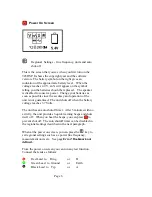
Page 5 – added reference to speaker disabled on low power 
Released to Art Department 

12/20/2000 

Changed dbrn0P noise limits 


Increased font size to 12pn 

Rev 8   

Resent to art department 


Changed screen label graphics to permit pdf printing 


Changed warning re effects of leakage current on opens P11 


Added statement that escape key cancels P21 


Changed shutdown beeps from 10 to 6 on P5 

Rev B   

Version 2.15 Changes 

2004/03/08 

Removed Ohms to Distance, restored Soak 

Summary of Contents for Dynatel 945DSP

Page 1: ... page 13 and 17 12 12 2000 Page 5 added reference to speaker disabled on low power Released to Art Department 12 20 2000 Changed dbrn0P noise limits Increased font size to 12pn Rev 8 Resent to art department Changed screen label graphics to permit pdf printing Changed warning re effects of leakage current on opens P11 Added statement that escape key cancels P21 Changed shutdown beeps from 10 to 6 ...

Page 2: ...Dynatel 945DSP Subscriber Loop Tester Instruction Manual March 8 2004 78 8130 3440 8 Rev B ...

Page 3: ...P Subscriber Loop Tester The Basis on which Conformity is being Declared The product identified above complies with the requirements of the above EU Directives by meeting the following standards EN 6100 4 2 Electrostatic Discharge EN 6100 4 3 Radiated RF Compatibilitity The CE mark was first applied in January 2001 The products described above comply with the essential requirements of the directiv...

Page 4: ...0 RESISTANCE 11 INSULATION SOAK 12 OPENS FAULT LOCATOR 13 OPENS SETUP 14 SEND TONE 16 LOAD COIL COUNT 17 DIALING 18 AUTODIALER 19 LOSS 20 NOISE AND POWER INFLUENCE 21 LONGITUDINAL BALANCE 22 SELF CALIBRATION 23 REGIONAL SETTINGS 24 TYPICAL MEASUREMENTS ON A POTS LINE 25 WARRANTY 26 INDEX TO SYMBOLS 29 ...

Page 5: ...ck Reference Card For Technical Service questions call 800 426 8688 in the US or Canada or contact your local 3M Representative For Warranty Repair or Ordering Information please refer to these sections near the end of this manual The Dynatel 945DSP comes with a carrying case and should remain in the case to give extra protection from shock and the environment Install the unit in the case by slidi...

Page 6: ...s drop below 3 7V Don t install used batteries in the unit If one battery in the pack is discharged more than the others it will effect the operation of the battery gauge and could cause the unit to switch off without the normal low battery warnings Screen The screen format is similar to the following for most functions Graphical icons on the right of the screen indicate the currently running test...

Page 7: ...ont label that corresponds to the actual test lead The labels and correspond to Ring Ground and Tip for North America and to B Earth and A for other countries All the tests on the 945DSP use these same connections so there is no need to rearrange leads between tests Red Lead to Ring or B Green Lead to Ground or Earth Black Lead to Tip or A Also rearranging the leads or moving the leads to a new pa...

Page 8: ...Page 4 Keypad The 945DSP Keypad has twenty keys The twelve blue keys are dual purpose In some tests they function as numeric keys but most of the time they are used to select a test ...

Page 9: ... selects measurement mode T or R or G Changes the setup of the currently running test Undo an action or back up to make corrections Adjusts contrast up Adjusts contrast down Test Keys Voltage Measurements Loop Current Ground Resistance and Ringers Resistance measurements Self Calibration Opens Length Test Transmit Tone and Load Counter Dialing mode AC Tests Loss Noise Power Influence and Longitudi...

Page 10: ...ation of the unit is not guaranteed The unit shuts off when the battery voltage reaches 3 7 Volts The unit has an auto shutoff timer After 5 minutes with no activity the unit provides 6 quick warning beeps and shuts itself off When you hear the beeps you can press to prevent shut off The auto shutoff timer can be disabled in the regional settings described in the next paragraph When at the power o...

Page 11: ...Page 7 Then press the desired test or control key ...

Page 12: ...emory Press the key to select between DC and AC volts The icon in the lower right area of the screen will change from DC to AC Press again to change back This symbol indicates that a high voltage has been detected between the test leads The 945DSP has opened an internal relay to protect itself from damage Use standard safety practices for disconnecting the test leads since high voltage may be pres...

Page 13: ...re red and black are connected to a working pair and the green lead is connected to ground See the next page for more detail To count ringers ensure the line is disconnected towards the CO and connect to the pair going toward the subscriber Verify the loop current is 0mA and press to get a count This warning indicates the current is greater than 110mA The 945DSP has opened an internal relay to pro...

Page 14: ...5DSP displays the resistance from the end of the green lead to the main ground at the central office The results on the screen are not live You must press to rerun the test and update the displayed result After completing the test press to return to the loop current screen or any other blue key to run another test This warning symbol indicates that the leads are not connected properly or the circu...

Page 15: ...nnect the clips to the pair going toward the subscriber Press and verify the loop current as 0mA the CO is disconnected Now press to reach the ringers counter This function counts up to five ringers connected tip to ring on a pair A standard ringer is defined a 0 47uF of capacitance Electronic ringers may show as less than 1 ringer Press the key to repeat the count When done press or any test key ...

Page 16: ...d to Ground lead or Black to Ground lead The boxes not currently live retain their last measurement on the screen from memory The measurement method used on the 945DSP is able to read resistance accurately even in the presence of foreign voltage After displaying an initial reading the 945DSP will check for foreign voltage and correct the reading if necessary A V appears on the screen to indicate v...

Page 17: ...ding to the lower box showing the insulation resistance of the black lead The key is used to update the initial reading The way the insulation resistance changes over time gives you an indication of the nature of the problem Wet cable faults tend to dry out when tested The final value will be higher than the initial saved value Oxidation tends to breakdown and become conductive over time which is ...

Page 18: ...g moves the live reading to one of the other boxes showing the ring length in the upper left box or the tip length in the lower left box The boxes not currently live retain their last measurement on the screen from memory Leakage on the pair effects the accuracy of the length reading For pairs under 1km 3000 in length the 945DSP will tolerate 20K ohm of leakage resistance and will measure to a dir...

Page 19: ... the 945DSP needs to know the amount of capacitance in a mile or kilometer of cable There are two separate values one for the mutual capacitance and one for the capacitance to ground Exact values are available from the cable manufacturer but for convenience a table of typical values is provided below This screen starts out with the cursor in the box for the ground capacitance value Use the blue nu...

Page 20: ... several typical cable types uF Mile nF Km Groun d Mutu al Groun d Mutu al Aircore 0 125 0 083 77 7 51 6 Jelly Filled 0 140 0 083 87 0 51 6 2 Pair Drop 0 155 0 083 96 1 51 6 5 Pair Drop 0 155 0 083 96 1 51 6 Tip This chart is printed on the back of the quick reference card in the plastic pouch of your carrying bag ...

Page 21: ...ation transmits an intermittent beeping tone at 577Hz You can use the key to adjust the volume level of the tone heard on the speaker but adjusting the volume doesn t effect the actual level transmitted on the pair Since you may want to transmit tone for some time the automatic shut off timer is extended to 30 minutes in this test You can disable the automatic shutoff timer in the regional setting...

Page 22: ...nutes to complete While the test is running the result box will be blank with a line of dots indicating progress The count will appear when the test is complete Press any test key or the key at any time if you wish to stop counting After the test is done or was stopped press the key to repeat the load coil count You must have at least 3000 feet 1000 meters of cable after each load coil for the Loa...

Page 23: ...reen then press again to go offhook Listen to the speaker for dial tone and then dial the desired number using the blue keys Press again to hang up or press to run loss and noise tests If you need to dial additional digits during a loss or noise test you can press the key to momentarily return to this screen dial the necessary digits and press to return to your loss or noise testing The 945DSP als...

Page 24: ...tored number Press again to move through the list of stored numbers A J When the desired number is displayed press to go offhook and dial the number The display will return to the normal manual dial screen in the previous section To add or change a stored number use the key to choose a storage location A J Key in the new or corrected number up to 14 digits long with the blue keys You can use the k...

Page 25: ...nd to near end using a tone between 200 Hz and 5 kHz Input impedance is 600 ohm The display shows you the level on top and the frequency underneath You must have first dialed a tone source or connected a separate instrument to generate the tone at the far end The signal on the pair is heard from the speaker You can use to adjust the volume Note that the 945DSP may limit the volume when the batteri...

Page 26: ...ine This screen automatically displays the difference between the two measurements computed balance in the lower box The 945DSP C uses a C Message filter displaying results in dBrnC units The 945DSP P uses psophometric weighting and will display results in dB r n P The signal on the pair is heard from the speaker You can use to adjust the volume Tip The key can be used as a shortcut for the key Pr...

Page 27: ...cle the longitudinal balance screen into view Use this function to display the longitudinal balance of the pair The pair should be disconnected at the far end or dialed to a quiet termination line A pair with good longitudinal balance 59 is more resistant to induced interference and exhibits low noise even in the presence of large amounts of power influence ...

Page 28: ...ee the following screen while the calibration is in progress After a few seconds delay the 945DSP will display the results of the self calibration This symbol indicates that the self calibration was successful After a few moments the unit returns to the power on screen Leads open short Red Black Green and try again This symbol indicates that the equipment is in need of repair The number in the sto...

Page 29: ...ens Meters Feet units of measurement for the opens length test Disable Enabled enable or disable the auto shutdown timer this shuts off the unit after 5 minutes of inactivity 60 Hz 50 Hz the AC power line frequency Note 945DSP P Psophometric units have an additional selection for noise units d B r n C or d B m 0 P In addition the final selection displays the model number and software date time sta...

Page 30: ...e Marginal Unacceptable Current 23 20 to 23 20 mA Loss 8 5 8 5 dBm Noise 20 20 to 30 30 dBrnC 70 70 to 60 60 dBm0p Power Inf 80 80 to 90 90 dBrnC 10 10 to 0 0 dBm0p Ground Res 25 25 Ohms Insulation Res 3M 3k to 3M 3k Ohms Balance 59 50 to 59 50 dB Note Ground Resistance can not be measured on floating tip or floating A switches such as the AT T 5ESS ...

Page 31: ...56 Black Red test lead alligator clip Single Nail 80 6111 6499 9 1157 Green test lead alligator clip Single Nail 80 6111 7358 6 1174 Bk Red leads alligator clip long Single Nail 80 6111 7357 8 1173 Green test lead alligator clip long Single Nail 80 6108 6395 5 Black red test lead 4 mm banana plug 1 5 m 80 6108 6399 7 Green test lead 4 mm banana plug 1 5 m CE 1006 8878 3 1152 945DSP SLT Soft Carry ...

Page 32: ...be considered defective if it satisfactorily fulfills the order or complies with the published specifications on standard catalog items This warranty does not extend to any of Seller s products which have been subjected to misuse neglect accident or improper applications nor shall it extend to units which have been repaired or altered outside of the Seller s factory nor to any associated instrumen...

Page 33: ...anteed Before using the equipment the buyer should determine the suitability of the product for the intended use and assumes all risk and liability whatsoever in connection with that use All statements or recommendations not contained in Seller s standard publications shall have no force or agreement unless an agreement signed by the officers of Seller and the above is made in lieu of all warranti...

Page 34: ...lect T or R or G P 7 Changes the setup of the currently running test P 5 Undo an action or backs up to make corrections P 5 Adjusts contrast up P 5 Adjusts contrast down P 5 Voltage Measurements P 7 Measures Loop Current P Error Bookmark not defined Resistance measurements P 10 Self Calibration P 23 Opens Length Test P 12 Transmits Tone P 16 Dialing mode P 18 AC Tests P 20 Loss Noise Power Influen...

Page 35: ... test P 9 Ground Resistance P 9 Insulation Soak P 12 In Soak saves the initial reading P 12 Transmit Tone P 16 Opens Length Test P 12 Noise P 21 PI P 21 Longitudinal Balance P 22 Touch Tone P 18 Dial Pulse P 18 Self Check Leads not connected 23 Hazardous Voltage Warning P 7 Hazardous Current Warning P Error Bookmark not defined In ground resistance indicates leads are not connected properly to a P...

Page 36: ...Telecom Systems Division 6801 River Place Blvd Austin Texas 78726 9000 USA http www mmm com telecom 3M 2000 ...

Reviews: