background image

3M 

1

/

8

 in. to 

3

/

4

 in. File Belt Sander 

Revision 022514

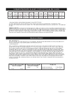
Recommended Airline

Size - Minimum

10 mm 

3/8 in

Recommended Maximum

Hose Length

8 meters 

25 feet

Air Pressure

Maximum Working Pressure 6.2 bar 90 psig
Recommended Minimum 

NA 

NA

Product Configuration/Specifications: 22,000 RPM File Belt Sander

*Declared noise levels; measurements carried out in accordance with standard EN ISO 15744:2008.
 ** Declared vibration levels in accordance with EN12096; measurements carried out in accordance with standard EN ISO 28662-1:1992; EN 60745-1:2006 
and EN 60745-2-4:2007, except that feed force was reduced to 10N +/- 5N due to the impracticality of operating this small tool at 30N +/- 5N as stated in the 
standard.

IMPORTANT NOTE: The noise and vibration values stated in the table are from laboratory testing in conformity with stated codes and standards and are not 
sufficient risk evaluation for all exposure scenarios. The actual exposure values and amount of risk or harm experienced to an individual is unique to each situation 
and depends upon the surrounding environment, the way in which the individual works, the particular material being worked, work station design, as well as 
upon the exposure time and the physical condition of the user. 3M™ cannot be held responsible for the consequences of using declared values instead of actual 
exposure values for any individual risk assessment.

Operating / Maintenance instructions

PRIOR TO THE OPERATION
The tool is intended to be operated as a hand held tool. It is always recommended that while using the tool, operators stand on a solid floor, in a secure position 
with a firm grip and footing. Be aware that the sander can develop a torque reaction. See the section “SAFETY PRECAUTIONS”.

Use a clean lubricated air supply that will give a measured air pressure at the tool of 6.2 bar (90 psig) when the tool is running with the lever fully depressed. It 
is recommended to use an approved 10 mm (

3

/

in) x 8 m (25 ft) maximum length airline. Connect the tool to the air supply as shown in Figure 1. Do not connect 

the tool to the airline system without an easily accessible air shut off valve. It is strongly recommended that an air filter, regulator and lubricator (FRL) be used 
as shown in Figure 1 as this will supply clean, lubricated air at the correct pressure to the tool. In any case appropriate air pressure regulators shall be used 
at all times while operating this tool where the supply pressure exceeds the marked maximum of the tool. Details of such equipment can be obtained for your 
tool distributor. If such equipment is not used, the tool should be manually lubricated. To manually lubricate the tool, disconnect the airline and put 2 to 3 drops 
of suitable pneumatic motor lubricating oil such as 3M™ Air Tool Lubricant PN 20451, Fuji Kosan FK-20, Mobil ALMO 525 into the hose end (inlet) of the tool. 
Reconnect tool to the air supply and run tool slowly for a few seconds to allow air to circulate the oil. If the tool is used frequently, lubricate it on a daily basis or 
lubricate it if the tool starts to slow or lose power. It is recommended that the air pressure at the tool be 6.2 bar (90 psig) while the tool is running so the maximum 
RPM is not exceeded. The tool can be run at lower pressures but should never be run higher than 6.2 bar (90 psig). If run at lower pressure the performance of the 
tool is reduced.

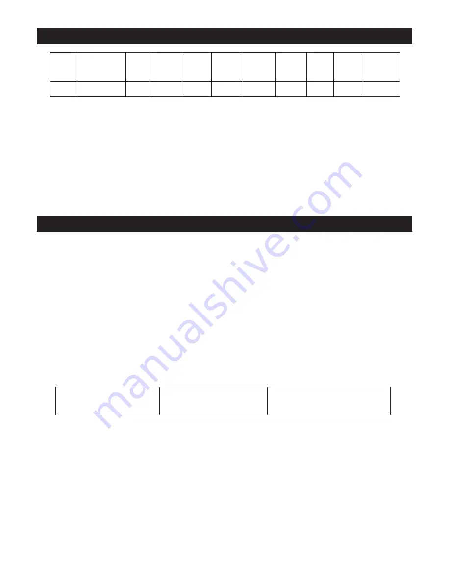
Model 

Number

Belt Size

in. (mm)

Motor 

Speed

(RPM)

Belt Speed

SFPM (smm)

Product 

Net Wt

lb (kg)

Height

in. (mm)

Length

in. (mm)

Width

in. (mm)

*Noise 

Level dBA 

Pressure 

(Power)

**Vibration 
Level m/s

2


(ft/s

2

)

**Uncertainty

K

m/s

2

28366

1

/

8

-

3

/

4

 x 18-24

(3-19 x 457-610)

22,000

4990 (1521)

2.8 (1.3)

2.93 (74.5)

14.57 (370)

5.95 (151.2)

81 (90)

<2.5 (<8.2)

N/A

Summary of Contents for File Belt Sander

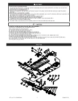
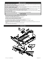
Page 1: ...requirements Wear protective apparel taking into consideration the type of work being done Never exceed marked maximum input pressure 90psi 62Mpa 6 2Bars Proper eye protection must be worn at all tim...

Page 2: ...t allow this tool to come into contact with electrical power sources as the tool is not insulated against electrical shock To reduce the risks associated with skin abrasion burns cuts or entrapment Ke...

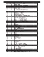
Page 3: ...TE ASSEMBLY FRONT 1 23 30632 CYLINDER 1 24 30633 ROTOR 1 25 30634 ROTOR VANE 4 26 30635 ENDPLATE ASSEMBLY REAR 1 27 30636 BEARING 2 SHIELDS 6 mm x 19 mm x 6 mm 1 28 30637 BELT HOUSING 1 29 30638 DRIVE...

Page 4: ...ubricated air supply that will give a measured air pressure at the tool of 6 2 bar 90 psig when the tool is running with the lever fully depressed It is recommended to use an approved 10 mm 3 8 in x 8...

Page 5: ...start handle in the event of any disruption of pressure do not attempt to re start until the disruption has been corrected 18 When tool is not in use store in a clean dry environment free of debris 19...

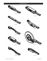
Page 6: ...3M 1 8 in to 3 4 in File Belt Sander 6 Revision 022514 File Belt Contact Arms 28368 28369 28370 28371 28372 28373 28374 28375 28376...

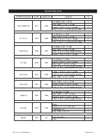
Page 7: ...1 8 in ID x 5 32 in Wide 2 Thin Style 28369 30667 Pad Platen Cork 1 2 in Wide 1 Bearing 1 4 in OD x 1 8 in ID x 7 64 in Wide 2 Wheel Contact 5 16 in Dia x 3 8 in Wide 1 Shaft 1 8 in Dia x 1 2 in Lg B...

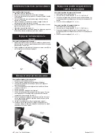
Page 8: ...r line 2 Loosen M4 cap screws A and B See Fig 4 3 Rotate the Belt Housing to the desired position Detents indicate the positions within a 360 degree range 4 Tighten M4 cap screws A and B To Adjust Han...

Page 9: ...cable operating instructions safety precautions and other procedures stated in the operating manual to be entitled to warranty coverage 3M shall have no obligation to repair or replace any tool or par...

Page 10: ...en service cesser imm diatement son utilisation et v rifier si des composantes sont us es ou endom mag es Corriger l anomalie ou remplacer la composante d fectueuse Si l outil produit toujours des vib...

Page 11: ...e le produit sur lequel on travaille Pour r duire le risque de tension dangereuse Cet outil n est pas isol contre les d charges ne pas le mettre en contact avec des sources d alimentation lectrique Po...

Page 12: ...30630 ESPACEUR 13 4 mm OD x 10 01mm ID x 3 2 mm PAIS 1 22 30631 PLAQUE DE FOND AVANT 1 23 30632 CYLINDRE 1 24 30633 ROTOR 1 25 30634 AILETTE DE ROTOR 4 26 30635 PLAQUE DE FOND ARRI RE 1 27 30636 6 mm...

Page 13: ...pi Se r f rer la figure 1 pour brancher l outil la source d air Ne pas brancher l outil au circuit d air comprim en l absence d un robinet de sectionnement d acc s facile Il est en outre fortement re...

Page 14: ...cesser imm diatement de l utiliser et le faire r parer 17 viter de faire tourner l outil librement sans prot ger les personnes ou les objets contre les projections de pon age ou de tampon 18 Ranger l...

Page 15: ...3M 1 8 in to 3 4 in File Belt Sander 15 Revision 022514 Bras de contact pour courroie 28368 28369 28370 28371 28372 28373 28374 28375 28376...

Page 16: ...de largeur 2 Style Mince 28369 30667 Coussinet platine de 1 2 po de largeur 1 Roulement billes 1 4 po de diam tre externe x 1 8 po de diam tre interne x 7 64 po de largeur 2 Roue de contact 5 16 po d...

Page 17: ...blage M4 A et B Voir la fig 4 3 Faire pivoter le logement de la courroie jusqu la position d sir e Les diff rentes positions sont indiqu es par des crans sur une plage de 360 degr s 4 Serrer les vis d...

Page 18: ...fication milieu de fonctionnement impropre installations inad quates erreur ou utilization fautive de l op rateur transformation ou modification maniement sans pr caution manque d entretien raisonnabl...

Page 19: ...ie Anwendung sofort und pr fen das Ger t auf verschlissene oder besch digte Komponenten Korrigieren oder ersetzen Sie die verd chtige Komponente Wenn das unnormale Ger usch oder die Vibration fortbest...

Page 20: ...ge isoliert ist Zur Verminderung des Risikos im Zusammenhang mit Hautabsch rfungen Verbrennungen Schnittverletzungen oder Erfassen durch drehende Teile Halten Sie H nde Haare und Kleidung entfernt vo...

Page 21: ...VORNE 1 23 30632 ZYLINDER 1 24 30633 DREHKOLBEN 1 25 30634 DREHKOLBENFL GEL 4 26 30635 ENDABDECKUNG HINTEN 1 27 30636 6 mmx 19 mm x 6 mm LAGER 2 SCHILDE 1 28 30637 BANDGEH USE 1 29 30638 ANTRIEBSSCHEI...

Page 22: ...eug gibt wenn das Werkzeug bei vollst ndig eingedr ckten Hebel l uft Es wird empfohlen einen zugelassenen Luftschlauch von 10 mm 3 8 Zoll x 8 m 25 ft L nge zu verwenden Schlie en Sie das Werkzeug an d...

Page 23: ...rmeiden 16 Wenn das Werkzeug nicht richtig zu funktionieren scheint nehmen Sie dieses sofort au er Betrieb und f hren das Ger t einer Wartung oder Reparatur zu 17 Lassen Sie den Startgriff sofort los...

Page 24: ...3M 1 8 in to 3 4 in File Belt Sander 24 Revision 022514 3M Kontaktarm f r Druckluftfeile 28368 28369 28370 28371 28372 28373 28374 28375 28376...

Page 25: ...ll breit 2 D nne Ausf hrung 28369 30667 Pad Vorlage 1 2 Zoll breit 1 Lager 1 4 Zoll AD x 1 8 Zoll ID 7 64 Zoll breit 2 Rad Kontakt 5 16 Zoll Durchmesser x 3 8 Zoll breit 1 Welle 1 8 Zoll Durchmesser x...

Page 26: ...ie M4 Kopfschrauben A und B Siehe Abb 4 3 Drehen Sie das Bandgeh use in die gew nschte Richtung Die Rasterung zeigt die Positionen innerhalb eines 360 Grad Bereichs an 4 Ziehen Sie die M4 Kopfschauben...

Page 27: ...g ltigen Betriebsanleitungen Sicherheitshinweisen und sonstigen Abl ufen verwenden die in der Bedienungsanleitung aufgef hrt sind 3M ist nicht zur Reparatur oder zum Austausch von Werkzeugen oder Tei...

Page 28: ...ota ruido o vibraci n anormales interrumpa su uso inmediatamente e inspecci nelo en busca de componentes gastados o da ados Corrija o cambie el componente del que sospeche Si el ruido o la vibraci n a...

Page 29: ...elacionados con voltaje peligroso No permite que esta herramienta entre en contacto con fuentes de energ a el ctrica ya que no est aislada contra choques el ctricos Para reducir los riesgos relacionad...

Page 30: ...mm OD x 19 mm OD x 0 02 mm GRUESO 1 21 30630 SEPARADOR 13 4 mm OD x 10 01 mm ID x 3 2 mm GRUESO 1 22 30631 CONJUNTO DE PLACA FRONTAL 1 23 30632 CILINDRO 1 24 30633 ROTOR 1 25 30634 ALETA ROTORA 4 26...

Page 31: ...a a la fuente de suministro de aire como se ilustra en la Figura 1 No conecte la herramienta al sistema de la l nea de aire sin tener una v lvula de cierre de aire f cilmente accesible Se recomienda a...

Page 32: ...17 En caso de cualquier interrupci n en la presi n suelte inmedi atamente la manija de arranque no intente usar nuevamente la herramienta sino hasta que la interrupci n haya sido corregida 18 Cuando...

Page 33: ...3M 1 8 in to 3 4 in File Belt Sander 33 Revision 022514 Brazos de Contacto de la Correa para Limar 28368 28369 28370 28371 28372 28373 28374 28375 28376...

Page 34: ...2 Estilo Delgado 28369 30667 Almohadilla Placa de 1 2 pulg de Ancho 1 Rodamiento 1 4 pulg de Di metro Externo x 1 8 pulg de Di metro Interno y 7 64 pulg de Ancho 2 Rueda Contacto de 5 16 pulg de Di m...

Page 35: ...cte la l nea de aire 2 Afloje los tornillos de cabeza M4 A y B Ver Fig 4 3 Gire la Caja de la Correa a la posici n deseada Los retenes indican las posiciones en un mbito de 360 grados 4 Ajuste los tor...

Page 36: ...en el manual de operaci n 3M no tendr obligaci n alguna de reparar o reemplazar cualquier herramienta o parte que falle debido a desgaste normal mantenimiento inapropiado limpieza inadecuada falta de...

Page 37: ...utiliza o e inspecione quanto a desgaste ou componentes danificados Corrija ou substitua o componente suspeito Se o ru do ou vibra o anormal ainda persistir retorne a ferramenta para a 3M para reparo...

Page 38: ...sta ferramenta entre em contato com fontes de energia el trica pois a ferramenta n o isolada contra choque el trico Para reduzir os riscos associados a abras o queimaduras cortes ou infiltra o na pele...

Page 39: ...02 mm ESPESSURA 1 21 30630 SPACER 13 4 mm OD x 10 01 mm ID x 3 2 mm ESPESSURA 1 22 30631 CONJUNTO DA PLACA FINAL FRENTE 1 23 30632 CILINDRO 1 24 30633 ROTOR 1 25 30634 P DO ROTOR 4 26 30635 CONJUNTO D...

Page 40: ...de ar conforme mostrado na figura 1 N o conecte a ferramenta ao sistema da linha de ar sem uma v lvula de bloqueio facilmente acess vel altamente recomendado que sejam usados um filtro de ar regulador...

Page 41: ...evidas precau es para proteger qualquer pessoa ou objeto contra perda de material abrasivo ou rupturas da base 18 Quando a ferramenta n o estiver em uso armazene a em ambiente seco e limpo livre de de...

Page 42: ...3M 1 8 in to 3 4 in File Belt Sander 42 Revision 022514 Bra os de contato de correia 28368 28369 28370 28371 28372 28373 28374 28375 28376...

Page 43: ...69 30667 Apoio Placa de 1 2 pol De largura 1 Rolamento DE Di metro Externo de 1 4 pol x 1 8 pol de DI Di metro Interno 7 64 pol de largura 2 Roda dia De contato de 5 16 pol c 3 8 pol de largura 1 Eixo...

Page 44: ...a 1 Desconecte a linha de ar 2 Solte os parafusos de cobertura M4 A e B Veja a Fig 4 3 Gire o Alojamento da Correia para a posi o desejada Os detentores indicam as posi es dentro de uma amplitude de 3...

Page 45: ...ara ter direito cobertura da garantia A 3M n o tem a obriga o de reparar ou substituir nenhuma ferramenta ou pe a que falhar devido a desgaste normal manuten o inadequada ou inapropriada limpeza inade...

Page 46: ...3M 1 8 in to 3 4 in File Belt Sander 46 Revision 022514 1 8 3 4 x 18 24 3 19 x 457 610 22 000 RPM 4990 1521 3M PPE ANSI Z87 1 90psi 62Mpa 6 2Bars 3M 3M 3M 3M 3M MSDS MSDS MSDS MSDS...

Page 47: ...t Sander 47 Revision 022514 ts MSDS MSDS 3M 001 800 362 3550 7 8 10 11 13 14 15 29 30 32 18 21 22 23 25 26 3 1 2 33 35 36 40 4 5 44 45 46 47 50 49 43 51 9 24 48 34 37 39 31 6 56 17 28 42 5 41 19 20 16...

Page 48: ...IM 25 4 OD x 19 OD x 0 05 1 21 30630 13 4 OD x 10 01 ID x 3 2 1 22 30631 1 23 30632 1 24 30633 1 25 30634 4 26 30635 1 27 30636 6 x 19 x 6 2 1 28 30637 1 29 30638 1 30 30639 1 31 30640 1 32 28799 1 33...

Page 49: ...5N 30N 5N 3M See the section SAFETY PRECAUTIONS 6 2 bar 90 psig 10 3 8 x 8 25 1 1 FRL 2 3 3M PN 20451 Fuji Kosan FK 20 Mobil ALMO 525 6 2 bar 90 psig RPM 6 2 bar 90 psig RPM SFPM smm dBA m s2 ft s2 K...

Page 50: ...D 1 2 XPA2240 WHEEL POSITION BLOCK 1 3 XPA2239 SHAFT REMOVAL TOOL 1 4 XPA2238 BEARING REMOVAL TOOL 3 8 ID 1 5 XPA2237 BEARING REMOVAL TOOL 1 4 ID 1 6 XPA2236 BEARING MOUNT TOOL 1 7 XPA2447 BEARING REM...

Page 51: ...3M 1 8 in to 3 4 in File Belt Sander 51 Revision 022514 28368 28369 28370 28371 28372 28373 28374 28375 28376...

Page 52: ...3 4 1 28368 30663 1 2 Pad 2 5 8 c 3 8 1 1 8 x 1 2 1 3 8 OD x 1 8 ID 5 32 2 28369 30667 1 2 1 3 8 OD x 1 4 OD x 1 8 ID 7 64 2 5 16 c 3 8 1 1 8 x1 2 1 28370 30668 3 8 OD x 1 8 ID 5 32 2 1 8 x 3 4 1 1 c...

Page 53: ...3M 1 8 in to 3 4 in File Belt Sander 53 Revision 022514 1 2 3 4 5 6 7 8 1 2 A B C 1 2 M4 A B 4 3 360 4 M4 A B 1 2 M4 B C 4 3 360 4 M4 B C 1 2 3 4 5 6 7 3 8 9 10 2 3 4...

Page 54: ...File Belt Sander 54 Revision 022514 Abrasive Systems Division 3M Center St Paul MN 55144 1000 www 3M com abrasives 3M 2014 3M 3M 3M 3M 3M 3M 3M 1 3M 3M 3M 3M 3M 3M 3M 3M 3M 001 800 362 3550 3M 3M 3M...

Reviews: