


7
8
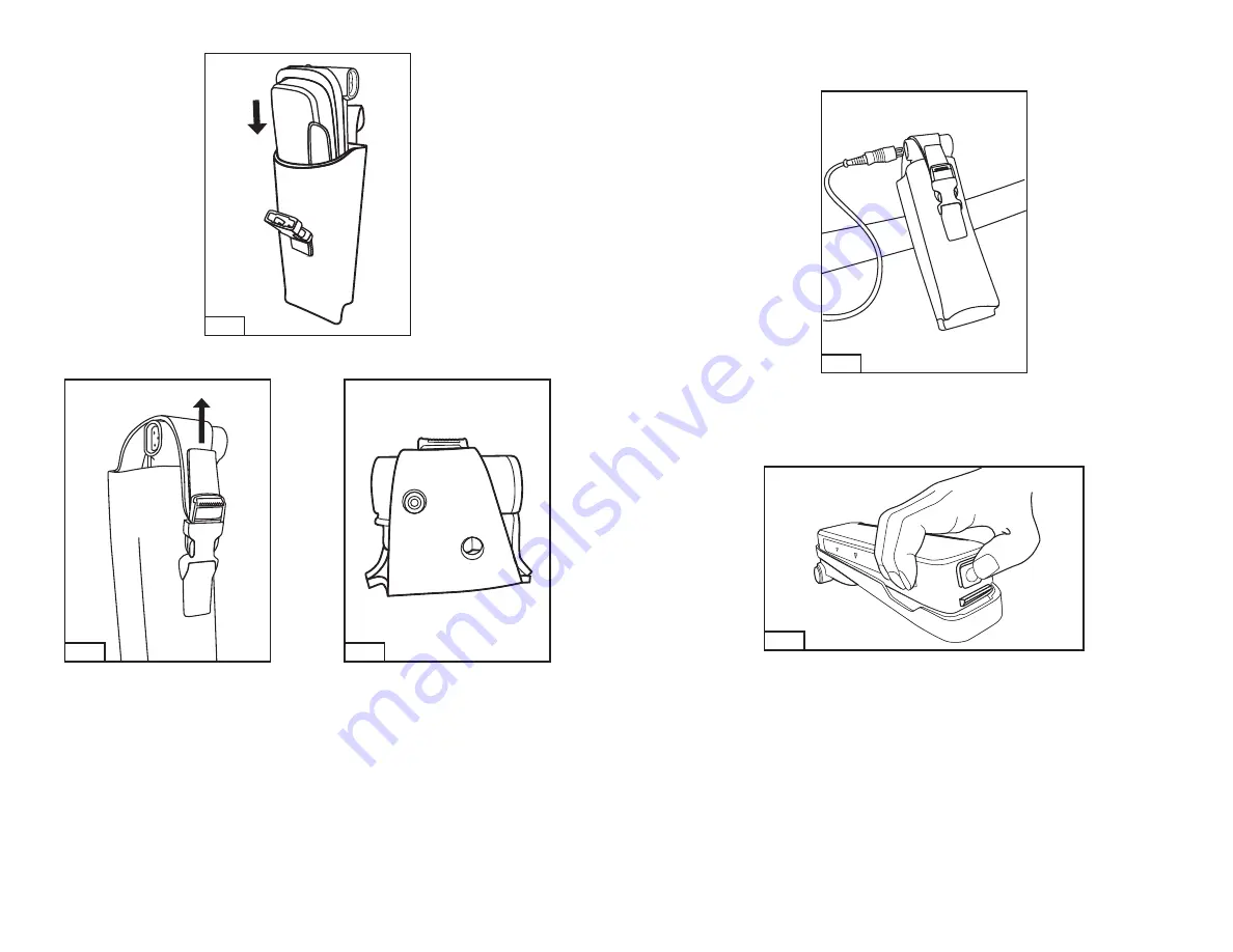
If choosing to wear the battery and holster on
left
side of waist belt, slide the TR-659 adapter with battery into the TR-656 heavy duty holster
with adapter side facing the belt loop (back) of the holster (Fig. 7).
Fig. 7
6. With the adapter and battery fully inserted into lower portion of holster, snap the buckle connecting the upper flap and lower portion of the
holster. Pull the leather strap located on the buckle to tighten top of holster for a snug fit (Fig. 8). Ensure that adapter indicator light can be
seen through one of the two holes located on the strap of the holster (Fig. 9).
Fig. 8
Fig. 9
Placing on waist belt and attaching the power cord
7. Thread the belt loop of the holster onto either the right or left side of the user’s waist belt, depending on the orientation chosen.
8. Connect the GVP-610 power cord to the TR-659 adapter (Fig. 10). Plug socket end of the power cord into the prong receptacle on the front
of the GVP-100 motor/blower. To power the motor/blower on, hold the power button on the adapter down for 1/2 second. When powered
on, the indicator light on the TR-659 should blink for approximately one second and then turn off.
Fig. 10
9. Position the holster assembly close enough to the motor/blower as to not strain the power cord, at the same time ensuring that the holster
assembly is placed in a location that allows the wearer to visually see the indicator light located on the top of the adapter.
To power the motor/blower off, hold the power button on the adapter down for 3 seconds. When there is approximately 15 minutes of charge
left on the TR-630 battery pack, the LED indicator light on the battery adapter will begin blinking.
Immediately exit the contaminated area
when the visual alarm (LED indicator light) on the adapter activates.
To detach the TR-630 battery from the TR-659 battery adapter, engage the blue release tab on the battery and pull upward (Fig. 11).
Fig. 11
The TR-657 easy clean holster which can be used in place of the TR-656 heavy duty holster. Please refer to the TR-659 battery adapter
User
Instructions
for instructions on how to assemble using this holster.
Headgear (Respiratory Inlet Cover)
H-Series, L-Series, L-SG-Series and S-Series headgear
Refer to the specific headgear
User Instruction
for information on attaching the breathing tube, donning and limitations of the headgear to be used.
6000DIN and 7800S full facepiece
1. Screw the threaded end without the 90 degree elbow into the GVP PAPR outlet port.
2. Remove the 3M™ Gasket Valve Plug 7890 from the
center port
of the full facepiece respirator (Fig. 12 and 13).
3. Ensure side inhalation ports are closed:
•
7800S Series facepiece:
Ensure 7890 plugs are in place
on each side port
of the respirator.
•
6000DIN Series facepiece:
Ensure a 6876 breathing tube gasket is in the center port and a 6895 inhalation port gasket and 6880
bayonet cap are attached and secure on
each of the side bayonet ports.
Replace gaskets and caps if missing or damaged.


