9
10
Fig. 12 7800S
Fig. 13 6000DIN
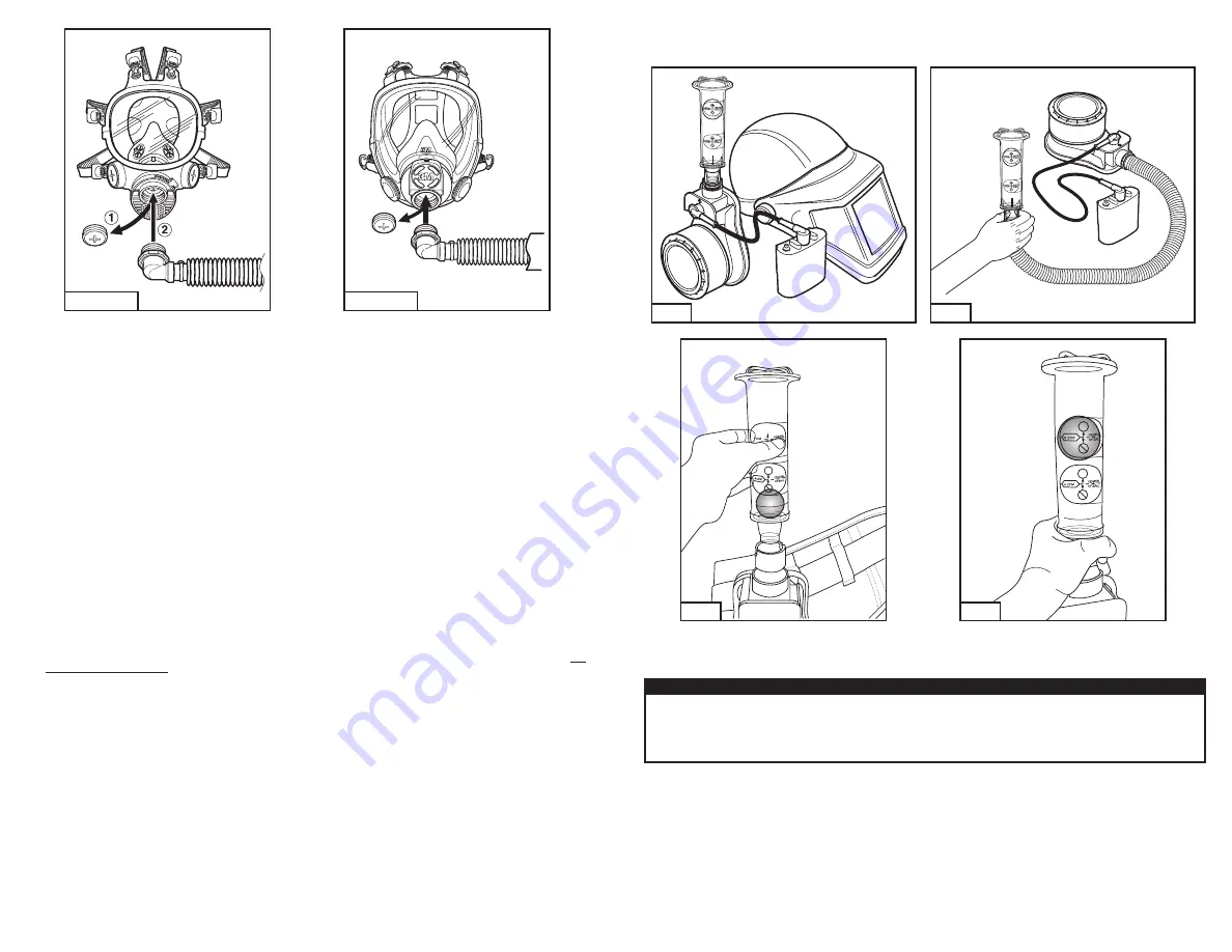
4. Screw GVP-123 breathing tube elbow adapter into the center port of the facepiece inlet of the respirator (Fig. 12 and 13).
5. Follow user donning and seal check procedures described in the
User Instruction
provided with the facepiece.
Motor Blower On and Off
• GVP-111: Press the gray on/off button on the top of the battery pack.
• BP-15: Turn the on/off switch on the top of the battery pack.
• TR-630 battery with TR-659 battery adapter: Press black on/off switch on side of battery adapter for 1/2 second to power on and for three
seconds to power off.
INSPECTION
Before each entry into a contaminated area, the following inspection must be performed to help ensure proper function of the respirator
system. Refer to the specific “Assembly” subsection of this
User Instructions
for proper assembly procedures.
NOTE:
There are no user serviceable parts inside the GVP PAPR assembly. The motor/blower unit must not be opened to attempt repairs.
Visual inspection
1. PAPR system: Visually inspect the entire PAPR system including the motor/blower, power cord, filter, breathing tube, battery pack, belt and
headgear. If parts are missing or damaged, replace them only with 3M™ GVP PAPR replacement parts before proceeding.
2. Battery pack: Confirm the battery pack is fully charged and the charge is sufficient for the duration of the work period. The PAPR
assembly power cord must be securely connected to the battery pack and motor blower. Inspect the battery pack for cracks or signs of
deterioration. Replace battery pack if damaged.
3. Power cord: Inspect the power cord ensuring that both the socket and prong ends are clean and free of signs of wear and corrosion.
Replace power cord if damaged.
4. Battery adapter: If using the TR-630 battery pack, ensure that the TR-630 battery is securely connected to the TR-659 battery adapter
before use. Ensure that the TR-659 battery adapter is in good condition and free of cracks, holes or signs of deterioration. Examine battery
connection pins and power cord receptacle for signs of wear or corrosion. Replace battery adapter if damaged.
5. Holsters: If using the TR-630 battery pack with TR-659 battery adapter, ensure that the battery pack and battery adapter combination are
securely seated in the holster. Examine the outside of the TR-656 heavy duty and/or the TR-657 easy clean holster for holes, ripped seams
or any other signs of wear. Replace holster if damaged.
6. Inlet and outlet port gaskets: Inspect the inlet and outlet port gaskets for cracks or excessive wear. If needed replace with new gaskets.
7. Filter/cartridge: The filter/cartridge should be properly installed and screwed in finger tight. If sparks or other hot particles are present, the
spark arrestor must be in place over the filter and GVP PAPR.
Failure to use the spark arrestor may allow the filter to be damaged
with subsequent user exposure to contaminated air.
8. Breathing tube: Examine the entire breathing tube for tears, holes or cracks. Bend the tube to verify it is flexible. The breathing tube should
connect firmly to the GVP motor blower. If damage is noted, replace with the appropriate breathing tube to match the respiratory headgear.
9. Examine the headgear per the recommendations in the headgear specific
User Instructions
.
10. Conduct an air flow check.
Airflow Check
This process should be followed prior to each use. Check the label on the air flow indicator to determine which test circle to use for the
airflow check.
1. Ensure the ball in the GVP-113 flow check indicator moves freely in its tube. Rinsing with clean water may help free a stuck ball. Allow the
tube and ball to dry prior to using.
2. Ensure that the filter selected is secured to the PAPR before testing airflow.
3. Attach the appropriate breathing tube to the PAPR outlet.
Exceptions:
• L-122 breathing tube: The 3M™ Adapter L-181 must be used instead of the breathing tube to check the airflow. The GVP-113 flow
meter will not fit into the end of the L-122 breathing tube.
• BT series breathing tube: The V-199 adapter must be used instead of the breathing tube to check the air flow. The GVP-113 flow meter
will not fit into the end of the BT series breathing tube.
4. Turn the PAPR motor blower on.
5. Insert the tapered end of the airflow meter:
a. L-181 adapter: Insert into the vinyl connector (Fig. 14) and hold vertically.
b. GVP-122, GVP-123 or H-115: Insert into the end of the breathing tube (Fig. 15) and hold vertically.
c. V-199: Insert into the end of the adapter (Fig. 16) and hold vertically using the thumb and forefinger to cover the two breathing tube
locking slots in the connector (Fig. 17).
6. Locate the position of the ball in the airflow meter.
Fig. 14
Fig. 15
OK
OK
Fig. 16
OK
OK
Fig. 17
7. Tight fitting facepieces: The ball should be located in or above the lower (4 cfm) tight fitting flow test circle.
8. Loose fitting headgear: The ball should be located in or above the higher (6 cfm) helmet and hood flow test circle (Fig. 17).
9. If the ball fails to move fully inside or above the flow test circle, insufficient airflow is being provided. Refer to “Troubleshooting” section of
User Instructions
.
W
WARNING
Failure to pass a user performance check and complete all necessary repairs before use
may adversely affect respirator performance
and result in sickness or death.
Before using a 3M™ GVP Respirator System, each person must read and understand the information in these
User Instructions
and the
User
Instructions
provided with the respirator headpiece to be used. Use of these respirator systems by untrained or unqualified persons, or use
that is not in accordance with these instructions,
may adversely affect respirator performance and may result in sickness or death.
ENTERING AND EXITING THE CONTAMINATED AREA
The following instructions are intended to serve as a guideline for the use of the 3M™ GVP PAPR. It is not to be considered all-inclusive, nor is
it intended to replace the policy and procedures for each facility.
Prior to entering the contaminated area, complete the inspection procedures listed in these
User Instructions
.
1. Turn the motor blower on.
2. Don the GVP assembly and headgear. Enter the work area.