background image

LIGHTFALLS by 3M™ + Todd Bracher Installation Guide - Sconce, Rev. C, Feb. 2014

Page 7

Installation Guide                                            LIGHTFALLS by 3M™ + Todd Bracher
                                                                                                                        Sconce

Installing the Product (cont.)

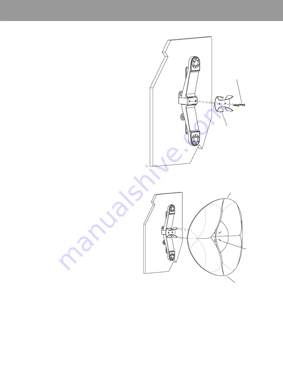
8. Install the Primary Reflector Standoff with the provided fasteners 

(See Figure 6).

Orient and Mount Primary Reflector

Align the slots in the primary reflector with the primary reflector 
standoff as shown (Figure 7), with the high sides of the reflector 
aligned with the Heatsink/LED assemblies. 

NOTE:  The reflective surface can be easily damaged. Take care 
not to scrape the tips of the metal standoff against the inside sur-
face of the primary reflector.

Press with enough force to snap the reflector into place on the 
reflector standoff. To produce a different lighting effect, re-install 
the reflector rotated by 90°.

Figure 6: Primary Reflector Standoff Installation

Hex Screws 
(6–32 x 3/4")

Primary Reflector 
Standoff

Figure 7: Primary Reflector Installation

High Side

High Side

Slots

Summary of Contents for LIGHTFALLS

Page 1: ... Product falling The Lightfalls fixture can weigh up to 1 pounds 0 5 kilograms Ensure that mounting brackets are adequately fastened to the load bearing point and able to carry the required load Always refer installation to a licensed electrician or certified lighting contractor DO NOT use the Product if it has incurred any physical damage Refer to a licensed electrician to check the Product befor...

Page 2: ...h this product vary by order Refer to your packaging slip for detailed information on the exact quantities provided Additional Materials The materials listed as required are required at a minimum Some sites may require additional materials not listed based on their installation Required Metal enclosure minimum dimensions 4 Gang Electrical Masonry Box 7 41 x 3 75 x 3 5 188 21mm x 95 25mm x 88 9mm o...

Page 3: ...ss light out of the fixture Table A Maximum Run Length Between LED Driver and Junction Box Plan Power Unit Placement and Cable Routing Select a location for the power unit satisfying local ordinances Determine how the cables will be routed through wall or ceiling For fixture to power unit distance greater than 25 feet Supply additional secondary wire Figure 1 Page 4 between the junction box and th...

Page 4: ...ed location For ceiling mounts mount the junction box above the power drop A cosmetic junction box cover is customer supplied Use provided harness to connect to LED assembly LED Assembly Plug Recpt LED Assembly Plug Recpt AC_L AC_N To additional supplies on same dimmer switch To additional supplies on same dimmer switch Dimmer Relay such as Lutron PP 120H or PP 277H depending on installation Dim D...

Page 5: ... one suggested ori entation 1 Choose the location and orientation for the Lightfalls Sconce 2 Mark the positions for the sconce bracket anchor point screw locations 3 Mark the position for the thick panel bushing location for wire routing 4 Install drywall concrete anchors as applicable and the thick panel bushing See Figure 2 5 Install the Sconce Bracket to the anchor points with customer supplie...

Page 6: ...once Installing the Product cont 6 Connect each Wire Harness to the Heatsink LED Assembly and route wire harness through bushing See Figure 4 7 Position both Heatsink LED Assemblies at the Sconce Bracket as shown Figure 5 Heatsink LED Figure 4 Wire Harness Connection Wire Harness Connector Figure 5 Heatsink LED Assembly Position ...

Page 7: ...igure 7 with the high sides of the reflector aligned with the Heatsink LED assemblies NOTE The reflective surface can be easily damaged Take care not to scrape the tips of the metal standoff against the inside sur face of the primary reflector Press with enough force to snap the reflector into place on the reflector standoff To produce a different lighting effect re install the reflector rotated b...

Page 8: ...t to repair the Lightfalls fixtures which do not have user serviceable parts Troubleshooting If the solutions below do not work for you please call 3M Technical Service at 1 888 650 3497 Table D Troubleshooting Related Documentation Please refer to the Lightfalls by 3M Todd Bracher Specification Sheet for product specifications and ordering information Problem Potential Cause What to Do LED does n...

Page 9: ... under the 3M Warranty as to Product that has been a modified or altered in any manner b damaged through contact with a person or thing misuse accident vandalism neglect or other action by anyone other than 3M c affected by environmental conditions such as power fluctuations improper LED driver or activity by animals or insects or d used not in compliance with all applicable standards and electric...

Reviews: