background image

3M™ MicroTouch™ Controller EX Serial Reference Guide 

21 


3M Touch Systems, Inc. Proprietary Information – TSD-29087 Rev D 

Caution:

 This document assumes you are familiar with firmware commands and how to 

use them. Executing some commands may alter the performance of your touch system 
and render it inoperable. You should be aware of the results before executing any 
firmware commands. 

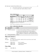
To optimize the performance of the touch controller and simplify the development of 
custom drivers, 3M Touch Systems recommends you use the commands listed in Table 5 
for current development. Using these commands ensures compatibility with all 3M™ 
MicroTouch™ controllers. 

Note:

  When you enter commands in terminal mode, precede each command with 

<CTRL> A to enter the start of header. 

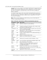
Table 5  Firmware Commands for EX Serial Controller Development 

Command   Code   Description 

Calibrate 
Extended 

CX 

Initiates an interactive 2-point calibration. 

Calibrate 
Raw 

CR 

Collects the raw X and Y coordinates before normal scaling, 
linearization, and filtering process. 

Format Raw 

FR 

Returns the signal level (amount of touch) of each of the four 
sensor corners in digital format. 

Format 
Tablet 

FT 

Outputs the X/Y touch coordinate data in a five-byte packet. 
Preferred for current development. 

Mode 
Stream 

MS 

Sends a continuous stream of X/Y coordinate data when you 
touch the sensor. 

Name  

NM 

Returns a controller identifier string. 

Null 
Command 

Queries the controller and waits for a response. 

Output 
Identity 

OI 

Identifies the controller type and the firmware version. 

Parameter 
Set 

Ppds[
b

Lets you adjust the communication parameters (parity, data 
bits, and stop bits) of the controller. 

Reset 

Initializes the hardware and the firmware, causes the 
controller to stop sending data, and recalculates the 
environmental conditions. 

Restore 
Defaults 

RD 

Returns the controller to the factory default operating 
parameters. Note: the serial port is reset to N81 format tablet 
and 2-point calibration is lost. 

Unit Type 
Verify 

UV 

Identifies the touch controller on your system. 

Summary of Contents for MicroTouch EX Series

Page 1: ...v D 3M MicroTouch Controller EX Serial Reference Guide Model Size Cased Connector EX112 1 X 2 NO AMP EX122 2 X 3 NO AMP EX142 2 X 3 YES AMP EX152 1 X 2 NO ZIF Read and understand all safety informatio...

Page 2: ...not warranted 3M Touch Systems Inc products and software are not specifically designed for use in medical devices as defined by United States federal law 3M Touch Systems Inc products and software sh...

Page 3: ...D Protection 10 EX Serial Controller Communication Connections 10 EX122 Sensor Cable Connections 11 EX112 Sensor Cable Connections 11 Mounting the Controller 12 Supplying Power to the Controller 13 Mo...

Page 4: ...Name Command 28 Null Command 29 Output Identity 29 Parameter Set 29 Reset 30 Restore Defaults 31 Unit Type Verify 31 Appendix A EX122 142 Controller Specifications Technical Specifications 34 Physica...

Page 5: ...committed to being a premier supplier in touch systems throughout the world As a 3M Touch Systems customer you are aware that we have strong internal programs that meet or exceed environmental regulat...

Page 6: ...e a damaged power supply Do not use a power cord that is frayed or otherwise damaged CAUTION To reduce the risks associated with improper disposal which if not avoided may result in minor or moderate...

Page 7: ...r website and technical support organization Visit the 3M Touch Systems website at http www 3M com touch where you can download touch software and drivers obtain regularly updated technical documentat...

Page 8: ......

Page 9: ...unting requirements Power requirements and options Status LED codes Overview of the EX Serial Controllers Note For complete specifications for each of these EX serial controllers refer to the appendic...

Page 10: ...cifications EX Serial Controller Communication Connections You will need a method of establishing the serial data communication between the controller and your system You can build your own or purchas...

Page 11: ...owards the serial cable Table 2 Sensor Cable Connector for EX122 Controllers Pin Wire Color Description 1 NOVRAM interface 2 NOVRAM interface 3 NOVRAM interface 4 5 VDC 5 6 7 Gray Green Orange Power s...

Page 12: ...ects to the flex tail shield which must not be grounded because the EX112 drives the flex tail shield with an AC waveform 4 Lower right LR corner 5 Lower left LL corner EX152 Sensor Cable Connections...

Page 13: ...nting hole near the sensor connector should be used to connect to chassis safety ground and must be attached by the shortest possible route to a good earth return chassis in all applications You can s...

Page 14: ...ctor screws To start up your system 1 Turn on your display and computer 2 Adjust the contrast and brightness to suit your personal preference and working environment 3 Adjust the horizontal and vertic...

Page 15: ...d from host NOV2 Error 8 7 Controller NOVRAM linearization data invalid Replace sensor or perform a 25 point linearization Contact Technical Support Reserved 9 8 Reserved EEPROM Error2 10 9 EEPROM is...

Page 16: ...Kernel 6 2 refer to the website for a complete listing You must be sure to install the correct software for your operating system 3M MicroTouch Software includes a control panel for setting your senso...

Page 17: ...ncludes the command syntax the default value how the command works and the expected response from the controller Overview of Firmware Commands Developers may use these commands when writing touch appl...

Page 18: ...urrent 3M Touch Systems product development and is the format used by all touch drivers written by 3M Touch Systems Refer to the Format Tablet command in the firmware reference section Note that 3M Mi...

Page 19: ...he hexadecimal code for the ASCII SOH control character is 01 To start the command sequence use the key combination Ctrl A A If you are working with an IBM PC compatible system the Ctrl A key combinat...

Page 20: ...rrectly The system parameters were not set up to allow command execution The controller does not support the command The terminator is the last character of each response string and is an ASCII carria...

Page 21: ...tion Calibrate Raw CR Collects the raw X and Y coordinates before normal scaling linearization and filtering process Format Raw FR Returns the signal level amount of touch of each of the four sensor c...

Page 22: ...d on these two points The Calibrate Extended command sets the calibration targets points inward from the corner of the video image Setting the targets inward makes the calibration process easier and m...

Page 23: ...ns the first calibration target inward from the lower left corner and the second calibration target inward from the upper right corner The following illustration shows how the calibration targets are...

Page 24: ...e calibration point Calibrate Raw Syntax SOH CR CR Description Allows the collection of raw signed X and Y coordinates before the normal scaling linearization and filtering processes The controller se...

Page 25: ...its in the status byte Byte 1 Table 7 Calibrate Raw Status Bits Bit Description Values S0 S5 Reserved S6 Proximity touch state 1 Sensor is being touched a touchdown or a continued touch 0 Sensor is no...

Page 26: ...se if the controller is not using an 8 bit communication mode To terminate Format Raw issue a Reset command The controller may return several bytes of data between the time you issue a Reset command a...

Page 27: ...so establishes the X and Y coordinate output as 14 binary bits providing a range of 0 to 16 383 The low order bits X3 X0 and Y3 Y0 are not significant in a 1024 by 1024 sensor because data can fluctua...

Page 28: ...to 0 touch liftoff the controller outputs one final set of X Y coordinate data with the bit equal to 0 and the X Y coordinate data equal to the last touch point S7 Packet synchronization Always 1 Mode...

Page 29: ...e version number Response SOH CcXxxx CR where Cc Two ASCII characters that describe the type of 3M MicroTouch controller Xxxx Four ASCII characters that indicate a build identifier Parameter Set Synta...

Page 30: ...n The settings are immediately written to NOVRAM and all future communication must occur at the new values It is possible to set the parameters to values that prevent future communication with the con...

Page 31: ...o the controller have rendered the sensor inoperative Table 12 EX Serial Controller Factory Default Settings Operating Parameter Default Baud Rate 9600 Serial Communication Settings N 8 11 Data Format...

Page 32: ...ormat SOH TtFfffSs CR where Tt Two ASCII characters that identify the controller type QM Serial controller Ffff Four ASCII characters that indicate the features supported by the controller R Indicates...

Page 33: ...ements and cable connectors The EX122 EX142 controlleris a compact 3 5 x 2 25 x 0 3 inches RS 232 serial controller This controller can be internally mounted in your display or enclosed in a molded pl...

Page 34: ...re RoHS Directive compliant 2011 65 EU Physical Dimensions Uncased 3 50 in x 2 30 in x 0 45 in 88 9 mm x 58 4 mm x 11 4 mm Cased 3 75 in x 2 50 in x 0 90 in 95 3 mm x 63 5 mm x 22 9 mm Board Level Fun...

Page 35: ...Class A Compliant Flicker EN 61000 3 3 Compliant Power Frequency Magnetic Field EN 61000 4 8 Class A Compliant Voltage Dips EN 61000 4 11 Class B 5 V Class C 70 V Compliant Voltage Interruptions EN 6...

Page 36: ...4 2 Normal Operation No false touches Compliant MTBF by MIL Std 217F Calculation 740 000 Hours Touch System Parameters Accuracy vs Dynamic Temperature Change tested at 0 deg C to 60 deg C with a 0 5 d...

Page 37: ...ntroller specifications such as power requirements environmental requirements and cable connectors The EX112 EX152 controller is a compact RS 232 serial controller This controller can be internally mo...

Page 38: ...components from suppliers other than 3M Touch Systems All components in the manufacture of electronic controllers are RoHS Directive compliant 2011 65 EU Physical Dimensions Uncased 2 55 in x 1 30 in...

Page 39: ...B Compliant ESD Susceptibility IEC 61000 4 2 Class 1 Compliant Surge EN 61000 4 5 Class B Compliant Harmonics EN 61000 3 2 Class A Compliant Flicker EN 61000 3 3 Compliant Power Frequency Magnetic Fie...

Page 40: ...allowed Compliant 27 kV Air Discharge Class 1 per section 9 of IEC 61000 4 2 Normal Operation No false touches Compliant MTBF by MIL Std 217F Calculation 700 000 Hours Touch System Parameters Accurac...

Page 41: ...3M MicroTouch Controller EX Serial Reference Guide 41 3M Touch Systems Inc Proprietary Information TSD 29087 Rev D...

Reviews: