background image

30 


3M™ MicroTouch™ Controller EX Serial Reference Guide 


3M Touch Systems, Inc. Proprietary Information -- 29087v03 

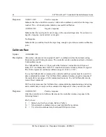
Examples:


<SOH>PN813<CR> 

Sets the serial line to no parity, eight data bits,


one stop bit, and 4800 baud. 

<SOH>PN81<CR> 

Sets the parity, data bits, and stop bits; leaves the baud at its 
previous value. 

Caution:  

The settings are immediately written to NOVRAM, and all future 

communication must occur at the new values. It is possible to set the parameters to values 
that prevent future communication with the controller. 

Response:


<SOH>

0

<CR> Positive 

response 


Reset 

Syntax:


<SOH>

R

<CR> 

Description:


Initializes the hardware and the firmware, causes the controller to stop sending data, and 
recalculates the environmental conditions (for example, stray and offset values). The 
Reset command also cancels the Format Raw, Calibrate Raw, and Calibrate Extended 
commands and returns the controller to normal operation. 

3M Touch Systems recommends that the host system issue a Reset command whenever 
the host system is powered on and is attempting to establish communication with the 
controller. 

The amount of time needed to execute a Reset command ranges from 225 milliseconds to 
800 milliseconds. Therefore, the application program should wait and be sure it receives 
the command response before issuing another command to the controller following the 
reset. 


Response:


<SOH>

0

<CR> Positive 

response. 


Restore Defaults 

Syntax:


<SOH>

RD

<CR> 

Description:


Returns to the factory default operating parameters. The Restore Defaults command 
copies the 3M Touch Systems factory default parameters from ROM to the non-volatile 
memory (NOVRAM) and then executes a Reset command. 

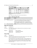
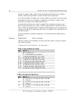
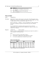
Table 12 lists the factory defaults for the EX serial controller. The Restore Defaults 
command is useful in situations where inadvertent commands to the controller have 
rendered the sensor inoperative. 


Summary of Contents for MicroTouch EX112

Page 1: ...ystems Inc Proprietary Information 29087v03 3M MicroTouch Controller EX Serial Reference Guide For EX122 and EX112 Read and understand all safety information contained in this document before using this product 3 ...

Page 2: ...s is not warranted 3M Touch Systems Inc products and software are not specifically designed for use in medical devices as defined by United States federal law 3M Touch Systems Inc products and software should not be used in such applications without 3M Touch Systems Inc express written consent User should contact its sales representative if User s opportunity involves a medical device application ...

Page 3: ...rotection 10 EX Serial Controller Communication Connections 10 EX122 Sensor Cable Connections 11 EX112 Sensor Cable Connections 11 Mounting the Controller 11 Supplying Power to the Controller 12 Mounting the Sensor 13 Turning On Your System 13 Status Light LED Diagnostics 13 Installing 3M MicroTouch Software 15 Chapter 3 3M MicroTouch EX Serial Controller Communications Overview of Firmware Comman...

Page 4: ...3 Name Command 28 Null Command 28 Output Identity 29 Parameter Set 29 Reset 30 Restore Defaults 30 Unit Type Verify 31 Appendix A EX122 Controller Specifications Technical Specifications 34 Physical Dimensions 34 Appendix B EX112 Controller Specifications Technical Specifications 38 Physical Dimensions 38 ...

Page 5: ...mier supplier in touch systems throughout the world As a 3M Touch Systems customer you are aware that we have strong internal programs that meet or exceed environmental regulations of our customers and the regions in which we conduct business What You Need to Know This document assumes you are familiar with firmware commands and how to use them Executing some commands may alter the performance of ...

Page 6: ... damaged power supply Do not use a power cord that is frayed or otherwise damaged CAUTION To reduce the risks associated with improper disposal which if not avoided may result in minor or moderate injury from ground water contamination Dispose of components in accordance with federal state and local regulations To reduce the risk of possible environmental contamination which may result in minor or...

Page 7: ...ebsite and technical support organization Visit the 3M Touch Systems website at http www 3M com touch where you can download touch software and drivers obtain regularly updated technical documentation on 3M Touch Systems products and learn more about our company Whenever you contact Technical Support please provide the following information Touch display size part number and serial number Current ...

Page 8: ......

Page 9: ...le connections Mounting requirements Power requirements and options Status LED codes Overview of the EX Serial Controllers Note For complete specifications for each of these EX serial controllers refer to the appendices at the end of this manual The EX serial controllers and sensors are supplied separately A 25 point linearization procedure has been performed to determine the physical properties o...

Page 10: ...fications EX Serial Controller Communication Connections You will need a method of establishing the serial data communication between the controller and your system You can build your own or purchase the standard 3M MicroTouch RS 232 serial cable P N 7310101 Table 1 describes the pins for this cable which connects to a serial communication COM port on the PC Table 1 COM Connections for EX Serial C...

Page 11: ...Upper left UL corner Lower left LL corner EX112 Sensor Cable Connections The sensor cable has a 5 pin single row locking female connector that plugs into the controller Table 3 describes the pins on this connector Table 3 Sensor Cable Connector for EX112 Controllers Pin Wire Color Description 1 Upper left UL corner 2 Upper right UR corner 3 Cable shield drain wire Connects to the flex tail shield ...

Page 12: ...rnal power 5V to 12 V DC through the 2 pin power input connector pin 2 5V to 12 V and pin 1 RTN A square pin indicator on the bottom of the board marks pin 1 Internal power 5V to 12V DC through a custom serial cable configuration External power 5 V DC from a wall mount power supply Note To avoid possible damage to one or both of the power supplies do not supply both internal power and external pow...

Page 13: ...g environment 3 Adjust the horizontal and vertical position controls on the display to center the image on the screen Status Light LED Diagnostics 3M MicroTouch controllers are highly reliable units however there may be occasions when the controller does not perform exactly as you expected The EX serial controller provides diagnostic feedback with a light emitting diode LED on the component side o...

Page 14: ...rom host NOV2 Error 8 7 Controller NOVRAM linearization data invalid Replace sensor or perform a 25 point linearization Contact Technical Support Reserved 9 8 Reserved EEPROM Error2 10 9 EEPROM is not working Reload program code NOV5 Error 11 10 Controller ID is not valid Restore defaults If fault persists replace controller NOV6 Error 12 11 Interface configuration values are not valid Restore def...

Page 15: ...rnel 6 2 refer to the website for a complete listing You must be sure to install the correct software for your operating system 3M MicroTouch Software includes a control panel for setting your sensor preferences and a diagnostic utility If you are experiencing problems with the sensor you can use the diagnostic utilities provided to locate the controller and test the sensor For more information on...

Page 16: ......

Page 17: ...opers may use these commands when writing touch applications developing custom drivers or touch configurations or testing their touch systems Developers can issue commands to initialize the controller select operating modes and execute diagnostic functions Most sensor users do not have to use firmware commands to use their touch systems For example users can use MT 7 software to calibrate the sens...

Page 18: ...eters to N81 Operating Mode The operating mode specifies the conditions under which the controller sends the X Y touch coordinates input data packet to the host system Mode Stream is the default operating mode for the EX serial controller In Mode Stream the controller sends a continuous stream of data packets when the sensor is touched The controller sends the data as long as a touch continues on ...

Page 19: ...ays follows the header consists of ASCII uppercase letters and numbers only printable characters The terminator is the last character of each command string and is an ASCII carriage return CR An ASCII CR control character is 0D hexadecimal To enter a carriage return ending the command sequence use Enter or the key combination Ctrl M M This chapter lists each command as a string of ASCII control ch...

Page 20: ...l The value returned in the response will be the ASCII control character for a carriage return displayed on the screen as the cursor moving to the next line In this chapter responses are shown as a string of ASCII characters consisting of a header the response and a terminator as follows SOH Response CR Controller Initialization To initialize the EX serial controller for new development 3M Touch S...

Page 21: ...ouch coordinate data in a five byte packet Preferred for current development Mode Stream MS Sends a continuous stream of X Y coordinate data when you touch the sensor Name NM Returns a controller identifier string Null Command Z Queries the controller and waits for a response Output Identity OI Identifies the controller type and the firmware version Parameter Set Ppds b Lets you adjust the communi...

Page 22: ...e Setting the targets inward makes the calibration process easier and more accurate Guidelines for Calibrate Extended Here are several guidelines for using the Calibrate Extended command The controller uses the data immediately before liftoff to register a calibration touch Therefore you can touch the sensor move your finger to the target hold for a few seconds and then lift off Instructing users ...

Page 23: ...on targets are calculated Calibrate Extended Procedure To use the CX command 1 Enter the Calibrate Extended CX command The controller sends an initial acknowledgment of SOH 0 CR 2 Touch the sensor at a lower left target which is located 12 5 1 8 in from the corner of the video image The controller returns an acknowledgment of SOH 1 CR This is a positive response If you receive a negative response ...

Page 24: ...aw mode The Calibrate Raw data is a 5 byte packet that includes 1 status byte and 4 bytes of binary X Y coordinate data Each X Y coordinate includes 10 binary bits and 1 sign bit The 10 bits represent coordinates within a range of 1024 to 1023 To use the Calibrate Raw command the controller and host system must be in an 8 bit data communication mode The Calibrate Raw command returns a negative res...

Page 25: ...s one final set of X Y coordinate data with the bit equal to 0 and the X Y coordinate data equal to the last touch point S7 Packet synchronization Always 1 Diagnostic Command Syntax SOH DX CR Description This command requests that the controller check for sensor failures such as broken corners broken wires etc Response SOH 0 CR Positive response SOH 1 CR Command not supported SOH 2 CR Failure dete...

Page 26: ... Reset after approximately 10 seconds has passed Use the Format Raw command for diagnostics Use Format Tablet for standard sensor operation Response SOH 0 CR Positive response After the controller is in Format Raw mode the controller returns a continuous response in the following format 41 byte packet 41 byte packet 41 byte packet Table 8 General Packet Formats Byte Bits 0 7 1 b0 b6 Reserved b7 Sy...

Page 27: ...nd therefore may not be completely accurate To use Format Tablet the controller and host system must be in an 8 bit data communication mode The Format Tablet command returns a negative response if the controller is in 7 bit format Response SOH 0 CR Positive response With the controller in Format Tablet mode touching the sensor causes the controller to return a response in the following format SXxY...

Page 28: ... sensor The controller continues to send data as long as you touch the sensor The controller sends the data even if the touch is stationary and unchanging The format of the coordinate data depends on the last format command received by the controller Response SOH 0 CR Positive response Name Command Syntax SOH NM CR Description This command returns a string of characters to help identify the contro...

Page 29: ... communication parameters parity data bits and stop bits of the controller Optionally you can change the communication rate by appending an additional character to the command string Upon execution of the Parameter Set command the controller automatically stores the new settings the current operating mode and the current data format in NOVRAM The communication parameters of the host system must ma...

Page 30: ...and Calibrate Extended commands and returns the controller to normal operation 3M Touch Systems recommends that the host system issue a Reset command whenever the host system is powered on and is attempting to establish communication with the controller The amount of time needed to execute a Reset command ranges from 225 milliseconds to 800 milliseconds Therefore the application program should wai...

Page 31: ...mmand you must recalibrate your sensor using a 2 point calibration Response SOH 0 CR Positive response Unit Type Verify Syntax SOH UV CR Description Responds with an 8 character identity string This string identifies the type of controller currently attached to the system lists the features supported by the controller and outputs the status of the controller hardware a self test code Response Retu...

Page 32: ...haracters that provide status information about the controller hardware The two characters represent one byte Each character is in the range 0 to 9 and A to F Table 2 defines the meaning of each bit LED minus 1 in the status byte Each bit can be set to 1 or 0 where 1 Error 0 No error 00 No diagnostic errors normal response ...

Page 33: ...quirements and cable connectors The EX122 controller is a compact 3 5 x 2 25 x 0 3 inches RS 232 serial controller This controller can be internally mounted in your display or enclosed in a molded plastic case 3 75 x 2 5 x 0 9 inches and mounted to the back or side of your display The following figures show the overall dimensions of the EX122 controller and the locations of the mounting holes and ...

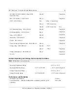
Page 34: ... RoHS Directive compliant 2002 95 EC Physical Dimensions Uncased 3 50 in x 2 30 in x 0 45 in 88 9 mm x 58 4 mm x 11 4 mm Cased 3 75 in x 2 50 in x 0 90 in 95 3 mm x 63 5 mm x 22 9 mm Board Level Functions Power 5 VDC 80 mA typical 100 mA maximum 5 regulation 50 mVpp maximum ripple and noise 12 VDC 85 mA typical 100 mA maximum 10 regulation 50 mVpp maximum ripple and noise Regulatory Requirements C...

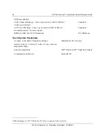
Page 35: ...ass A Compliant Flicker EN 61000 3 3 Compliant Power Frequency Magnetic Field EN 61000 4 8 Class A Compliant Voltage Dips EN 61000 4 11 Class B 5 V Class C 70 V Compliant Voltage Interruptions EN 61000 4 11 Class C Compliant UL cUL Compliant Ambient Operating and Storage Environmental Conditions Note All humidity is non condensing Operating Temperature Range 40 C to 70 C Operating Humidity Range 3...

Page 36: ...ss 1 per section 9 of IEC 61000 4 2 Normal Operation No false touches Compliant MTBF by MIL Std 217F Calculation 740 000 Hours Touch System Parameters Accuracy vs Dynamic Temperature Change tested at 0 deg C to 60 deg C with a 0 5 deg C minute temperature ramp Maintains 99 0 Accuracy Sensor Compatibility 3M MicroTouch Capacitive Sensors Communications Protocol Serial RS 232 2 ESD discharges to a 3...

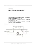
Page 37: ... controller specifications such as power requirements environmental requirements and cable connectors The EX112 controller is a compact RS 232 serial controller This controller can be internally mounted in your display The following figures show the overall dimensions of the EX112 controller and the locations of the mounting holes and connectors Figure 3 EX112 Touch Controller ...

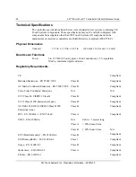
Page 38: ...DC 85 mA typical 110 mA maximum 5 regulation 50 mVpp maximum ripple and noise Regulatory Requirements CE Compliant Radiated Emissions EN 55022 1998 Class B Compliant AC Mains Conducted Emissions EN 55022 1998 Class B Compliant Telco Lines Conducted Emissions N A N A FCC Class B CISPR22 Class B Class B Compliant VCCI Class B ITE Emissions Japan Class B Compliant AS NZS 3548 1995 CISPR 22 Class B IT...

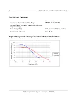
Page 39: ...erating Humidity Range 36 C 0 95 RH 36 C refer to Figure 4 Storage Temperature Range 50 C to 85 C Storage Humidity Range 36 C 0 80 RH 36 C refer to Figure 4 Performance and Reliability Minimum Touch Duration 5 4 msec Touch Resolution Maximum addressable coordinates generated by the controller 16K x 16K ESD Susceptibility3 8 kV Contact Discharge Class 2 per section 9 of IEC 61000 4 2 1 false touch ...

Page 40: ...h System Parameters Accuracy vs Dynamic Temperature Change tested at 0 deg C to 60 deg C with a 0 5 deg C minute temperature ramp Maintains 99 0 Accuracy Sensor Compatibility 3M MicroTouch Capacitive Sensors Communications Protocol Serial RS 232 Figure 4 Storage and Operating Temperature with Humidity Conditions ...

Reviews: