2
VI. Jumpering
Jumper wires must be plastic-insulated .5 mm (24 AWG)
g with a maximum O.D. of 1.1 mm (.042 inches) to insure
reliable connections with multiple insertions. See Figure 75.
A. Running Jumper Wires
1. Pull wire from spool to either Feeder (green cover) or
Distribution (blue cover) Module.
2. Split pair over black rib with TIP left, RING right and
SNAP into BOTH front and rear catch areas on cover.
See Figures 76 and 77.
3. Impact both Tip and Ring of jumper wire using
ONLY the 4055 Insertion Tool. Tool will impact only
when held perpendicular to module. See Figure 78.
Remove excess wire by pulling through front catch.
(Tool may not impact if used on previously impacted
jumper wire or on contact with no wire.)
4. Follow wire raceways formed by Module mounts.
a. DO NOT run wire across face of Modules.
b. Jumper wires in Cover slots 1-12 go behind left
Mounts and those in slots 13-25 go behind right
Mounts.
c. Run jumper wire along back of Module towards
nearest edge.
d. Slip jumper wire behind Mounts and run over wire
run guide.
e. Slip behind Mounts on proper module bank and on to
other Module.
f. Always allow 76 mm (3 inches) total SLACK in
jumper wire.
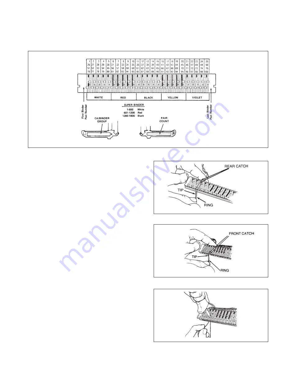
Figure 75.
Figure 76.
Figure 77.
Figure 78.
Summary of Contents for MS2 4000 Series
Page 2: ......
Page 5: ... ...
Page 21: ...21 Figure 46 Figure 47 ...
Page 36: ...36 D Supply Information ...
Page 37: ...37 ...
Page 39: ...39 ...


