background image

22

4.0 Use

4.1 

BEFORE EACH USE:

 Before each use of this fall protection equipment carefully inspect it to assure it is in good working 

condition. Check for worn or damaged parts. Ensure all bolts are present and secure. Check that the lifeline is retracting 

properly by pulling out the line and allowing it to slowly retract. If there is any hesitation in retraction the unit should be 

removed from service and destroyed. Inspect the lifeline for cuts, frays, burns, crushing and corrosion. Check locking 

action by pulling sharply on the line. See the Inspection and Maintenance Log (Table 3) for inspection details. Do not use 

if inspection reveals an unsafe condition.

4.2 

AFTER A FALL:

 Any equipment which has been subjected to the forces of arresting a fall or exhibits damage consistent 

with the effect of fall arrest forces as described in Table 3, must be removed from service immediately and destroyed.

4.3 

BODY SUPPORT:

 A full body harness must be worn when using SRDs. 

4.4 

MAKING CONNECTIONS:

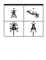
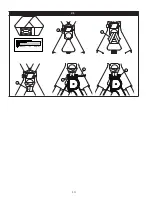
 Figure 11 illustrates harness and anchorage connections for SRD Fall Arrest Systems. When 

using a hook to make a connection, ensure roll-out cannot occur (see Figure 5). Do not use hooks or connectors that 

will not completely close over the attachment object. Do not use non-locking snap hooks. The anchorage must meet the 

anchorage strength requirements stated in Section 1. Follow the manufacturer’s instructions supplied with each system 

component.

4.5 

WRAPBACK ATTACHMENT:

 WrapBack snap hooks operate in the same manner as many conventional snap hooks. 


See Figure 11-D: Gripping the hook in one hand, the index finger depresses the locking mechanism (E). With the thumb, 

the gate latch is pulled back (F). As the gate latch is pulled back, the gate will open. Release the grip and the gate will 

close. Wrap the WrapBack portion of the lifeline around an appropriate anchor (G), then open the gate of the WrapBack 

snap hook and pass the WrapBack web portion of the lifeline through the snap hook. The lifeline may only pass through 

the WrapBack hook once. Make sure the Wrapback portion of the lifeline is captured and the gate closes completely.


;

Only the WrapBack hook may be used to snap back onto the WrapBack portion of the SRD Lifeline. When 

installed, the WrapBack hook must contact the heavy web section (WrapBack portion of the lifeline). If the 

anchor structure is so large that the WrapBack hook contacts the lifeline above the WrapBack portion of 

the lifeline, a different anchor structure must be used. Failure to heed this warning may result in equipment 

malfunction, serious injury, or death.


;

A minimum setback distance of 0.6m (2 ft) is required when using Nano-Lok Edge SRDs incorporating a 

WrapBack attachment. 


;

Never connect the WrapBack snap hook of one SRD to the lifeline of another SRD or lanyard. Failure to heed 

this warning may result in equipment malfunction, serious injury or death.

4.6 OPERATION:

 Prior to use, inspect the SRD as described in Section 2.2 and the schedule in Table 2.  Figure 11 shows 

system connections for typical SRD applications. Connect the SRD on the back of a Full Body Harness per the instructions 

in Section 3. Connect the Hook (D) or Carabiner to a suitable anchorage. Ensure connections are compatible in size, 

shape, and strength. Ensure hooks are fully closed and locked. Once attached, the worker is free to move about within the 

recommended working area at normal speeds. If a fall occurs the SRD will lock and arrest the fall. Upon rescue, remove 

the SRD from use. When working with an SRD, always allow the lifeline to recoil back into the device under control.

4.7 

TWIN SRD INTERFACE 100% TIE-OFF:

 When two SRDs are mounted side-by-side on the back of a Full Body Harness, 

the SRD Fall Arrest System can be used for continuous fall protection (100 % tie-off) while ascending, descending, or 

moving laterally (see Figure 11B). With the Lanyard Leg of one SRD attached to an anchorage point, the worker can move 

to a new location, attach the unused Lanyard Leg of the other SRD to another anchorage point, and then disconnect from 

the original anchorage point. The sequence is repeated until the worker reaches the desired location. Considerations for 

Twin SRD 100% tie-off applications include the following:

• 

Never connect both SRD Lanyards to the same anchorage point. (See figure 12a)

• 

Connecting more than one connector into a single anchorage (ring or eye) can jeopardize compatibility of the 

connection due to interaction between connectors and is not recommended.

• 

Connect each SRD Lanyard to a separate anchorage point. (See figure 12b)

• 

Each connection location must independently support 2,248 lbs (10 kN) or be an engineered system, as with a 

Horizontal Lifeline.

• 

Never connect more than one person at a time to the Twin SRD system. (See figure 12c)

• 

Do not allow the Lanyards to become tangled or twisted together as this may prevent them from retracting.

• 

Do not allow any lanyard to pass under arms or between legs during use. 

4.8 

HORIZONTAL SYSTEMS:

 In applications where the SRD is used in conjunction with a horizontal system (i.e. Horizontal 

Lifeline, Horizontal I-Beams Trolley), the SRD and horizontal system components must be compatible. Horizontal systems 

must be designed and installed under the supervision of a qualified engineer. Consult the horizontal system equipment 

manufacturer’s instructions for details.

Summary of Contents for Nano-Lok Edge 3500209

Page 1: ...420 3500232 B 2 4 m 8 ft 2 140 310 191 420 3500233 B 2 4 m 8 ft 2 140 310 191 420 3500234 B 2 4 m 8 ft 2 140 310 191 420 3500236 B 2 4 m 8 ft 2 140 310 191 420 3500237 B 2 4 m 8 ft 2 140 310 191 420 3500238 B 2 4 m 8 ft 2 140 310 191 420 3500253 B 2 21 m 7 3 ft 2 140 310 191 420 3500235 D 2 73 m 9 ft 2 140 310 191 420 3500250 B 2 4 m 8 ft 2 140 310 191 420 3500259 B 2 1 m 7 ft 2 140 310 191 420 35...

Page 2: ...2 2 xxxxxxxxxxx xxxxxxxxxxx xxx xxx xxx xx xxx xxx xxx xx G H I G H J K L K H I K J L L M M M L 3 A B FC FF DD SF FC C FC H ...

Page 3: ...0 6 2 0 3 1 2 1 7 1 8 6 1 5 5 1 2 4 0 9 3 0 6 2 0 3 1 2 4 8 0 3 1 0 6 2 0 9 3 1 2 4 1 5 5 FC V H 101 140 kg 221 310 lbs 2 1m 7 ft 2 4 m 8 ft 4 3 m 14 ft 4 9 m 16 ft 3 0 m 10 ft 3 7 m 12 ft 5 5 m 18 ft 6 1 m 20 ft m ft m ft 2 1 7 1 8 6 1 5 5 1 2 4 0 9 3 0 6 2 0 3 1 2 4 8 2 4 8 2 1 7 1 8 6 1 5 5 1 2 4 0 9 3 0 6 2 0 3 1 2 1 7 1 8 6 1 5 5 1 2 4 0 9 3 0 6 2 0 3 1 2 4 8 0 3 1 0 6 2 0 9 3 1 2 4 1 5 5 FC ...

Page 4: ...6 2 0 3 1 2 1 7 1 8 6 1 5 5 1 2 4 0 9 3 0 6 2 0 3 1 2 4 8 0 3 1 0 6 2 0 9 3 1 2 4 1 5 5 FC V H 59 100 kg 130 220 lbs 1 8 m 6 ft 3 0 m 10 ft 3 7 m 12 ft 4 3 m 14 ft 4 9 m 16 ft 5 5 m 18 ft FC 2 7 9 2 4 m 8 ft m ft m ft 2 1 7 1 8 6 1 5 5 1 2 4 0 9 3 0 6 2 0 3 1 2 4 8 2 4 8 2 1 7 1 8 6 1 5 5 1 2 4 0 9 3 0 6 2 0 3 1 2 1 7 1 8 6 1 5 5 1 2 4 0 9 3 0 6 2 0 3 1 2 4 8 0 3 1 0 6 2 0 9 3 1 2 4 1 5 5 2 7 9 2 ...

Page 5: ... 1 7 1 8 6 1 5 5 1 2 4 0 9 3 0 6 2 0 3 1 2 4 8 2 4 8 2 1 7 1 8 6 1 5 5 1 2 4 0 9 3 0 6 2 0 3 1 FC H V 141 191 kg 311 420 lbs 2 7 9 2 7 9 2 7 9 m fy 2 1 7 1 8 6 1 5 5 1 2 4 0 9 3 0 6 2 0 3 1 2 4 8 0 3 1 0 6 2 0 9 3 1 2 4 1 5 5 m ft 2 1 7 1 8 6 1 5 5 1 2 4 0 9 3 0 6 2 0 3 1 2 4 8 2 4 8 2 1 7 1 8 6 1 5 5 1 2 4 0 9 3 0 6 2 0 3 1 3 0 m 8 ft 3 7 m 12 ft 4 3 m 14 ft 4 9 m 16 ft 5 5 m 18 ft 6 1 m 20 ft 6 ...

Page 6: ...6 C 5 6 A B C 7 ý NO 90 90 þ OK 8 C B A A B C ...

Page 7: ...0 16 6 5 2 17 0 5 4 17 8 5 6 18 6 5 9 19 3 2 0 6 4 6 15 0 4 7 15 6 4 9 16 0 5 0 16 6 5 2 17 2 5 5 18 0 5 6 18 6 3 0 9 4 4 14 6 4 6 15 0 4 7 15 6 4 9 16 0 5 0 16 6 5 1 17 0 5 3 17 6 4 0 9 4 3 14 0 4 4 14 6 4 6 15 0 4 7 15 6 4 9 16 0 5 0 16 6 C 59 100 kg 130 220 lbs B ft m 0 0 0 1 0 3 2 0 6 3 0 9 4 1 2 5 1 5 6 1 8 A 2 0 6 4 0 13 0 4 1 13 5 4 2 13 10 4 3 14 3 4 5 14 8 4 6 15 1 4 7 15 6 3 0 9 3 8 12 4...

Page 8: ... 1 13 6 4 2 13 11 4 4 14 5 4 5 14 9 4 1 2 3 5 11 6 3 6 11 11 3 8 12 4 3 9 12 9 4 0 13 3 4 2 13 8 C A B C D 101 140 kg 221 310 lbs D 0 9m 3 B ft m 0 0 0 1 0 3 2 0 6 3 0 9 4 1 2 5 1 5 6 1 8 A 2 0 6 4 6 15 0 4 7 15 6 4 9 16 0 5 0 16 6 5 2 17 2 5 5 18 0 5 6 18 6 3 0 9 4 4 14 6 4 6 15 0 4 7 15 6 4 9 16 0 5 0 16 6 5 1 17 0 5 3 17 6 4 0 9 4 3 14 0 4 4 14 6 4 6 15 0 4 7 15 6 4 9 16 0 5 0 16 6 C 9 ...

Page 9: ...9 10 1 B A 2 C G D C 3 F F C A E D 4 F F ...

Page 10: ...10 11 A B A C B D D C C C B A F E D G 12 A B C ...

Page 11: ...11 13 14 15 E E E E xxxx xxxx xxx C D A E B A A 16 17 18 A B C D C A B D A ...

Page 12: ...12 19 A 2 1 B 3 C D E Nano Lok edge F Nano Lok edge G ...

Page 13: ...13 20 2 1 2 1 A B 2 1 2 1 C ...

Page 14: ...14 21 1 2 3 5 4 6 ...

Page 15: ... the SRD Avoid sudden or quick movements during normal work operation This may cause the device to lock up Ensure that fall protection systems subsystems assembled from components made by different manufacturers are compatible and meet the requirements of applicable standards including the ANSI Z359 or other applicable fall protection codes standards or requirements Always consult a Competent and ...

Page 16: ...Fabric Web Vectran Polyester Stitching Nylon Thread Swivel Zinc Plated Steel Harness Connector Aluminum Alloy Frame and Stainless Steel Locking Pin Fasteners Zinc Plated Alloy Steel Screws Stainless Steel Rivets Locking Pawls Stainless Steel Main Shaft Stainless Steel Motor Springs Stainless Steel Wrapback Web Kevlar Dyneema Connector Specifications Description Model Number Material Gate Opening G...

Page 17: ...els Capacity Range 59 kg 140 kg 130 lbs 310 lbs Maximum Arresting Force 6 kN 1 350 lbs Average Arresting Force 4 kN 900 lbs Claimed Maximum Arresting Distance1 2 1 m 7 ft Minimum Fall Clearance Required 4 2 m 14 ft when falling over an edge Maximum Free Fall2 1 5 m 5 ft Minimum Setback Distance 0 m 0 ft 0 6 m 2 ft for WrapBack models 1 Assumes the SRL is mounted directly above overhead the end use...

Page 18: ...s occur when the anchorage point is not directly above the point where a fall occurs The force of striking an object in a swing fall may cause serious injury see Figure 3A Minimize swing falls by working as directly below the anchorage point as possible Figure 3B Working away from the anchorage point Figure 3C will increase the impact of a swing fall and increase the required Fall Clearance FC Fal...

Page 19: ... this equipment must be self locking Ensure all connections are compatible in size shape and strength Do not use equipment that is not compatible Ensure all connectors are fully closed and locked 3M connectors snap hooks and carabiners are designed to be used only as specified in each product s user s instructions See Figure 6 for examples of inappropriate connections Do not connect snap hooks and...

Page 20: ... your Leading Edge application be sure work area parameters are within the Minimum Setback Distance Maximum Free Fall Distance and Minimum Fall Clearance Required when Falling Over an Edge as indicated on the SRD LE labeling For straight line connections the WrapBack SRD should only be attached to a rigid anchor point if used in a Leading Edge application Leading Edge Fall Clearance Calculation Th...

Page 21: ...nd loop straps around the Shoulder Straps and secure The Red Band G on the knob end of the Harness Interface Locking Pin will be exposed if the Harness Interface is unlocked To avoid accidental release of the connection always make sure the Harness Interface is locked before using the Harness and attached SRD Failure to do so could result in injury or death 5 Alternate Attachment Strap The Nano Lo...

Page 22: ...ious injury or death A minimum setback distance of 0 6m 2 ft is required when using Nano Lok Edge SRDs incorporating a WrapBack attachment Never connect the WrapBack snap hook of one SRD to the lifeline of another SRD or lanyard Failure to heed this warning may result in equipment malfunction serious injury or death 4 6 OPERATION Prior to use inspect the SRD as described in Section 2 2 and the sch...

Page 23: ...soap solution Position the SRD so excess water can drain out Clean labels as required Clean the Lifeline with water and mild soap solution Rinse and thoroughly air dry Do not force dry with heat The lifeline should be dry before allowing it to retract into the housing An excessive buildup of dirt paint etc may prevent the lifeline from fully retracting back into the housing causing a potential fre...

Page 24: ... or broken fibers Check for tears abrasions heavy soiling C mold burns D or discoloration Inspect stitching Check for pulled or cut stitches Broken stitches may be an indication that the Energy Absorber has been impact loaded and must be removed from service Wire Rope Lifelines Figure 17 Inspect wire rope for cuts kinks A broken wires B bird caging C welding splatter D corrosion chemical contact a...

Page 25: ...struée est nécessaire pour que le dispositif auto rétractable se bloque normalement Évitez les mouvements brusques ou rapides durant le travail normal Ce type de mouvements pourrait provoquer le blocage du dispositif Assurez vous que les systèmes sous systèmes de protection antichute assemblés à partir de composants fabriqués par différents fabricants sont compatibles et répondent aux exigences de...

Page 26: ... Composants internes Acier inoxydable et alliage d acier Ligne de vie Ligne de vie Câble galvanisé 7 x 19 de 3 16 po Amortisseur de choc Recouvrement Polyester et nylon Sangle Vectran polyester Couture Fil en nylon Pivot Acier zingué Connecteur du harnais Cadre en alliage d aluminium et goupille d arrêt en acier inoxydable Attaches Vis galvanisée en alliage d acier rivets d acier inoxydable Clique...

Page 27: ...rêt maximale 6 kN 1 350 lb Force d arrêt moyenne 4 kN 900 lb Distance d arrêt maximale déclarée1 2 1 m 7 pi Dégagement de chute minimal requis 4 2 m 14 pi en cas de chute par dessus un bord Chute libre maximale2 1 5 m 5 pi Distance de recul minimale 0 m 0 pi 0 6 m 2 pi pour les modèles à enroulement 1 Présume que la ligne de vie autorétractable est montée directement au dessus de l utilisateur fin...

Page 28: ...u point où la chute s est produite Si un objet est heurté pendant le mouvement de balancier la force peut être importante et causer des blessures graves voir la Figure 3A Il est possible de réduire les chutes avec mouvement de balancier en travaillant le plus directement possible sous le point d ancrage Figure 3B Travailler à distance du point d ancrage Figure 3C augmentera l impact d une chute av...

Page 29: ...u point d attache C 2 7 CONNEXIONS Les crochets à ressort et les mousquetons utilisés avec cet équipement doivent être autoverrouillables S assurer que toutes les connexions sont compatibles en ce qui concerne leur taille leur forme et leur résistance N utiliser aucun équipement non compatible S assurer que tous les connecteurs sont bien fermés et verrouillés Les connecteurs 3M crochets à ressort ...

Page 30: ...vent être requises Pendant la planification d une application comportant un bord d attaque veiller à ce que les paramètres de la zone de travail soient dans les limites de la distance de recul minimale de la distance maximale de chute libre et du dégagement de chute minimal requis lors d une chute par dessus un bord comme l indique l étiquette du dispositif autorétractable pour bord d attaque Pour...

Page 31: ...rface du harnais sera exposée si l interface du harnais est déverrouillée Pour éviter le dégagement accidentel du harnais toujours s assurer que l interface du harnais est verrouillée avant d utiliser le harnais et le Dispositif autorétractable qui y est attaché Tout manquement à ces directives peut provoquer des blessures ou la mort 5 Sangle de fixation de rechange Les sangles de fixation du disp...

Page 32: ...nroulement Ne jamais fixer le crochet à ressort à enroulement d un dispositif autorétractable à la ligne de vie d un autre dispositif autorétractable ou d une autre longe Ne pas tenir compte de cet avertissement peut entraîner un mauvais fonctionnement de l équipement ainsi que des blessures graves ou la mort 4 6 FONCTIONNEMENT Avant l utilisation inspecter le Dispositif autorétractable tel que dé...

Page 33: ... d eau et de savon doux Rincer et sécher complètement à l air Ne pas soumettre l équipement à un séchage accéléré à la chaleur La ligne de vie doit être sèche avant de la laisser se rétracter dans le boîtier Une accumulation excessive de saletés de peinture ou autre peut empêcher la ligne de vie de se rétracter entièrement dans son boîtier et causer ainsi un danger potentiel de chute libre 6 2 SER...

Page 34: ...ure 16 Inspecter les sangles et ou les lignes de vie à câble elles doivent être exemptes de coupures A d effilochage B ou de fibres cassées Inspecter l équipement afin de détecter des déchirures abrasions souillures importantes C moisissures brûlures D ou décolorations Inspecter les coutures afin de détecter toute séparation ou coupure des coutures Les coutures brisées peuvent indiquer que l amort...

Page 35: ... se réserve le droit d exiger le retour du produit dans ses installations afin d évaluer la réclamation de garantie Cette garantie ne couvre pas les dommages au produit résultant de l usure d un abus ou d une mauvaise utilisation les dommages subis pendant l expédition le manque d entretien du produit ou d autres dommages en dehors du contrôle de 3M 3M jugera seul de l état du produit et des option...

Page 36: ... 29 Kitashinagawa Shinagawa ku Tokyo Phone 81 570 011 321 Fax 81 3 6409 5818 psd jp mmm com WEBSITE 3M com FallProtection I S O 9 0 0 1 FM534873 EU DECLARATION OF CONFORMITY 3M com FallProtection DOC U S PRODUCT WARRANTY LIMITED REMEDY AND LIMITATION OF LIABILITY WARRANTY THE FOLLOWING IS MADE IN LIEU OF ALL WARRANTIES OR CONDITIONS EXPRESS OR IMPLIED INCLUDING THE IMPLIED WARRANTIES OR CONDITIONS...

Reviews: