background image

15

Shut-Off procedure:

RO membrane cartridge will need to be changed at least every twenty four (24) months. Pre and Post Filter cartridges must be replaced every six 
(6) months. 

1.  Unplug system from the wall outlet, which will shutoff feedwater to RO system.

2.  Open Pre-fi lter sample valve until fl ow stops and left pressure gauge reaches 0 psi to relieve pressure. 

Pre-Filter and Post Filter Cartridge (blue label) Replacement:

1.  Push and hold yellow tab to release cartridge locking mechanism while simultaneously rotating cartridge to the left. 

2.  Using both hands and holding the cartridge from the bottom, rotate the cartridge a quarter turn to the left and gently pull down. 

NOTE: A small amount of water will drain from manifold as cartridge is removed.

3.  Remove red sanitary cap from new cartridge. Ensure o-rings are seated into their grooves and lubricate with water. Install with a quarter turn to 

the right until cartridge come to a complete stop. NOTE: Cartridges are keyed to fi t in proper location only. 

RO Membrane Cartridge (green label) Replacement:

1.  Remove the reject tubing and the elbow from the RO membrane cartridge. (See Figure 1).

2.  Push and hold yellow tab to release RO membrane cartridge locking mechanism while simultaneously rotating RO membrane cartridge to the 

left.

3.  Using both hands and holding the RO membrane cartridge from the bottom, rotate the RO membrane cartridge a quarter turn to the left and 

gently pull down. NOTE: A small amount of water will drain from manifold as cartridge is removed.

Routine Maintenance Cartridge Change-out Instructions (Pre/ Post Filter and RO Membrane Cartridge)

WARNING

WARNING

Read entire manual. Failure to follow all guide and rules could cause personal injury or property damage.

• 

Check with your local public works department for plumbing codes. You must follow their guidelines as you install the water fi ltration system.

• 

Your water fi ltration system will withstand up to 125 pounds per square inch (psi) water pressure. If your water supply pressure is higher than 
80 psi, install a pressure reducing valve before installing the water fi ltration system.

To reduce the risk associated with choking:

• 

DO NOT allow children under 3 years of age to have access to small parts during the installation of this product.

To reduce the risk associated with the ingestion of contaminants:

• 

DO NOT use with water that is microbiologicaly unsafe or of unknown quality without adequate disinfection before or after the system. Systems certifi ed 
for cyst reduction may be used on disinfected water that may contain fi lterable cysts.

NOTICE

NOTICE

To reduce the risk associated with property damage due to water leakage or fl ooding:

• 

Read and follow Use Instructions provided with the original system prior to use of this replacement cartridge.

• 

Change the disposable fi lter cartridge at the recommended interval; the disposable fi lter cartridge MUST be replaced every 24 months or sooner.

• 

Failure to replace the disposable fi lter cartridge at recommended intervals may lead to reduced fi lter performance and failure of the fi lter, causing 
property damage from water leakage or fl ooding.

• 

Protect from freezing, remove fi lter cartridge when temperatures are expected to drop below 33° F (4.4° C).

• 

DO NOT install systems in areas where ambient temperatures may go above 110° F (43.3° C).

• 

DO NOT install on hot water supply lines. The maximum operating water temperature of this fi lter system is 100°F (37.8°C).

• 

DO NOT install if water pressure exceeds 125 psi (862 kPa). If your water pressure exceeds 80 psi (552 kPa), you must install a pressure limiting valve. 
Contact a plumbing professional if you are uncertain how to check your water pressure.

IMPORTANT NOTE:

The RO membrane cartridges have green labels and will only fi t into the head on the right side of the manifold (head has a green 3M label). 

Summary of Contents for ScaleGard HP

Page 1: ...manual with owner operator Owner Operator Please retain for operation and future instructions 3M Water Filtration Products Installation and Operation Instructions for ScaleGardTM HP Reverse Osmosis S...

Page 2: ...aution Statements 4 Parts List 5 Feedwater Requirements 6 Other Requirements 6 Equipment Set Up and Installation 7 System Start Up 10 Routine Maintenance 15 16 Troubleshooting Guide 17 Product Replace...

Page 3: ...is higher than 80 psi install a pressure reducing valve before installing the water filtration system An approved post filter and tank must be used with the RO system To reduce the risk associated wit...

Page 4: ...T install an appropriate pressure relief valve Pressure relief valve must be maintained and inspected every 6 months Contact a plumbing professional if you are uncertain how select install maintain a...

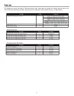
Page 5: ...ilter and RO with UK plug 6239304 220 240VAC w out Pre filter and RO with AU plug HF90 CL RO Pre Filter 1 5613529 HFRO 500 RO membrane 1 5626903 Equipment Components Sold Separately Description Quanti...

Page 6: ...PN 50 93201 If the particle count is 1000 counts ml for particles less than 2 micron size or turbidity is greater than the recommended 5 ntu limit then it may be required to consider different prefilt...

Page 7: ...leGard HP reverse osmosis base unit and 0 5 or larger tubing diameter is required to complete installation Figure 1 Plumbing Diagram Bypass Provided by Installer Check Valve Provided by Installer 1 2...

Page 8: ...with property damage due to water leakage or flooding Mount ScaleGardTM HP base unit in such position as to prevent it from being struck by other items being used in the area of installation Ensure t...

Page 9: ...Plumbing connections for the ScaleGardTM HP reverse osmosis system are now complete Install cartridge per instructions below Pre Filter and Post Filter Cartridge blue label Installation 1 Remove red s...

Page 10: ...ee Figure 1 page 7 2 Turn ON the feedwater supply by plugging system into electrical outlet 3 Open Pre Filter flush valve to vent air from system and flush for 10 gallons approximately 5 minutes If er...

Page 11: ...after the desired TDS value is reached Re adjust and check as needed See Figure 5 item 2 below 4 Lock the blending valve using the lock nut 5 After TDS is set drain RO tank System is now ready for use...

Page 12: ...BLUE BROWN Step Down Transformer 3 WIRE NUT 8 LEVER NUT 14 11 6 LEVER NUT 5 LEVER NUT 7 LEVER NUT TERMINAL BLOCK Output LED Color Meaning Normal Running Condition PWR Green On when the units power co...

Page 13: ...bar for 220 240VAC systems the unit is off on full tank 1 Unit will cycle on when tank switch senses 40 psi TOGGLE CYCLE 1 Motor Pump stop 2 2 second delay the inlet solenoid closes 3 1 second delay t...

Page 14: ...is is normal To reduce the risk associated with property damage due to water leakage or flooding Notice Take care when using pliers or pipe wrenches to tighten plastic fittings as damage may occur if...

Page 15: ...low their guidelines as you install the water filtration system Your water filtration system will withstand up to 125 pounds per square inch psi water pressure If your water supply pressure is higher...

Page 16: ...pressure 2 Release tubing 3 Cut off at least 1 4 from end 4 Reattach tubing 5 Confirm connection is leak free Figure 9 How to Use Push in Connectors 4 Remove sanitary cap from new RO membrane cartridg...

Page 17: ...e Check for 1 feedwater pressure 2 production flow rate 3 drain flow rate before replacing RO membrane Ensure drain line is not kinked or plugged Replace if needed RO membrane fouls high feed water ha...

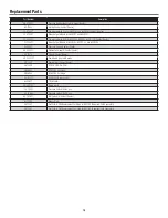
Page 18: ...ge Contact Dealer 60 125001 Permeate Solenoid Contact Dealer 85 9274 Shroud Contact Dealer 89 3220101 Pump Head Contact Dealer 89 2302 Pump Motor Contact Dealer 5613529 HF90 CL RO Pre Filter 5626903 H...

Page 19: ...19 Notes...

Page 20: ...1 year from the date of purchase The filter cartridge or membrane is warranted to be free from defects in material and manufacture for one 1 year No warranty is given as to the service life of any fi...

Reviews: