To use the 3M Heat Trace Bill of Materials Tool, visit
3M.ca/HeatTrace
18
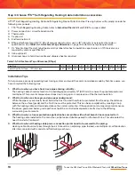
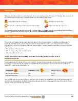
Installation Tips
To help ensure a properly operating heat tracing system and avoid the common mistakes made by first-time users, we
have compiled the following tips:
1.
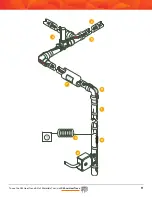
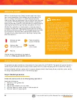
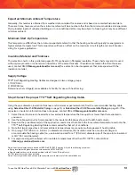
What to do when you have heat-trace pipe entering a facility:
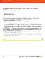
The heating cable should extend into the building approximately 12" (305 mm) to ensure the pipe temperature is
maintained. This prevents temperature drops due to air gaps or compression of the thermal insulation.
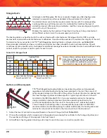
2.
What to do when an above ground pipe goes underground:
While the pipe may eventually travel below the frost line and therefore be protected from freezing, the distance
between the surface (grade) and the frost line must be protected. This can be accomplished by creating a loop
with the heating cable end terminated above the normal water line. If the application is temperature maintenance,
the above-grade and below-grade portions should be controlled as separate circuits due to the differing
surrounding environments.
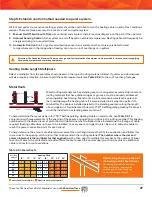
3.
What to do when a freeze protection application has a main line with a short branch line connected to it:
The heating cable installed on the main line can be looped (double passed) on the branch line. This eliminates the
need to install a T-splice kit.
4.
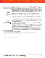
What to do when all heating cable power connection points need to be secured to the piping:
Heating cable should not pass through the air to travel to an adjoining pipe. Instead, use multiple circuit fabrication
kits interconnected with conduit and field wiring as shown.
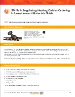
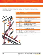
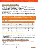
Step 4: Choose TTS™ Self-Regulating Heating Cable installation accessories.
A TTS™ Self-Regulating Heating Cable Self-Regulating Freeze Protection Heat Tracing System will typically include the
following components:
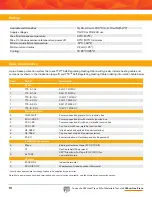
1. TTS™ Self-Regulating Heating Cable (refer to
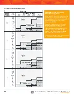
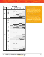
Selection Charts 1.2.1
and
1.2.2
for proper cable)
2. Power connection / circuit fabrication kits
3. Thermostats
4. T-splice kit
5. End termination kit
6.
BTape attachment tape (1/2" X 60 yd) secures cable to pipe; use on 12" intervals or as required by code or
specification. Use
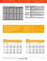
Table 1.5.1. Attachment Tape Allowance
on page 18 to determine tape requirements.
7. CL “Electric Heat Tracing” label (peel and stick label attaches to insulation vapor barrier on 10' intervals or as
required by code or specification.
8. Inline splice kit
9. Aluminum tape to hold down cable and disperse heat as required
Table 1.5.1: Attachment Tape Allowance (BTape)
Pipe Size
½"-1"
1¼"
1½"
2"
3"
4"
6"
8"
10"
12"
14"
Feet of Pipe/Roll of Tape – 180' roll of tape
360'
260'
220'
180'
150'
120'
90'
70'
60'
50'
40'
Summary of Contents for TTS-5-1-OJ
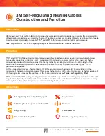
Page 7: ...To use the 3M Heat Trace Bill of Materials Tool visit 3M ca HeatTrace 7 2 2 2 2 2 3 3 3 3...
Page 8: ...To use the 3M Heat Trace Bill of Materials Tool visit 3M ca HeatTrace 8 Pipe Freeze Protection...
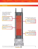
Page 11: ...To use the 3M Heat Trace Bill of Materials Tool visit 3M ca HeatTrace 11 4 5 6 7 9 1 8 3 2...

