To use the 3M Heat Trace Bill of Materials Tool, visit
3M.ca/HeatTrace
34
Information from IEEE Standard 515.1-1995
and ASHRAE)
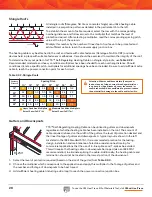
to simplify the selection process for determining the level
of protection required. An additional table can be found in
the Cable Spacing Selection Guide on page 39.
Creating a Materials List
The following five steps outline the selection process for a snow melting system using KSR™ Self-Regulating
Heating Cable.
Following each design step is an example that illustrates the process of evaluating, planning and specifying a snow
melting system.
While the example shown is small, the process would be the same regardless of the area to be protected. The design
examples include flat surfaces, stairs, a ramp, expansion joints in the concrete, and the need to bring power from a
specific location.
Determining the area that will require heat tracing is based somewhat on the traffic expected during snow and ice
accumulation periods, as well as the layout of the area and TTS™ Self-Regulating Heating Cables location relevant to
prevailing winds and susceptibility to drifting.
Then you must identify the existence of electric snow and ice melting heat tracing cable in the concrete curbs,
walkways, and paving portions of the project specification. In addition, the project drawings (both electrical and site
work) should include reference to the existence of electric heat tracing.
For example, the public/employee entrance to a facility is exposed to weather with only the area directly in front of the
entry doors covered by a roof. The building is adjacent to the concrete on two sides with the accessibility ramp (which
has a retaining wall) located on the third side. Snow removal can only be accomplished at the curb and parking area, a
choice found undesirable for various reasons.
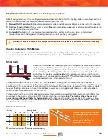
To maintain a clear entrance, the landing, stairs, ramp and approach area will require snow melting. The area in front
of the doors will be heat traced to also prevent accumulation from drifting and tracking.
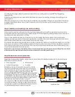
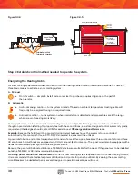
Step 1: Identify area requiring snow and ice melting.
Step 2: Determine level of protection.
Phone/Cable
Room
Landing
Approach
Partial Plan at Entry
Stairs
Curb
Ramp
Up
Up
Building Entry
Figure 3.1.1
Regardless of geographical location or size of area to be protected, the heating requirements for snow melting are
affected by four primary factors:
• Rate of snowfall
• Ambient temperature
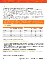
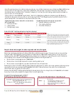
Establishing the level of protection required for a facility
requires an understanding of the type of service the area
will encounter and under what type of weather conditions
the snow and ice melting system must perform.1 3M
developed
Table
3.2.1
KSR™ Self-Regulating Heating Cable
spacing (using information from IEEE Standard 515.1-1995
and ASHRAE) to simplify determining and selecting the level
of protection required. An additional table can be found in
the Cable Spacing Selection Guide on page 37.
• Wind velocity
• Humidity
To create your materials list online, visit 3M.ca/HeatTrace.
Summary of Contents for TTS-5-1-OJ
Page 7: ...To use the 3M Heat Trace Bill of Materials Tool visit 3M ca HeatTrace 7 2 2 2 2 2 3 3 3 3...
Page 8: ...To use the 3M Heat Trace Bill of Materials Tool visit 3M ca HeatTrace 8 Pipe Freeze Protection...
Page 11: ...To use the 3M Heat Trace Bill of Materials Tool visit 3M ca HeatTrace 11 4 5 6 7 9 1 8 3 2...


