To use the 3M Heat Trace Bill of Materials Tool, visit
3M.ca/HeatTrace
To use the 3M Heat Trace Bill of Materials Tool, visit
3M.ca/HeatTrace
37
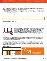
Expansion Joints:
Unless the slab is of monolithic construction, there will be
expansion or construction joints that must be taken into account to prevent damage
to the cable (
Figure 3.4.2
).
• Keep expansion joint kit use to a minimum by utilizing proper layout techniques.
• Mark drawings with locations of expansion and construction joints.
• Allow an extra 3' of KSR™ Self-Regulating Heating Cable for each expansion
joint kit.
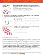
Stair Steps:
Because of the rugged yet flexible nature of KSR™ Self-Regulating
Heating Cable and the centre-to-centre spacing typical to most applications, difficult
areas such as steps can be easily accommodated.
• Tie KSR™ Self-Regulating Heating Cable to reinforcing steel in same manner as
open areas.
•
Serpentine across each tread; route up riser to next tread.
• Concrete can be placed in single pour.
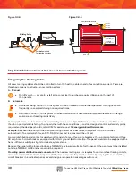
Determine a suitable location for the power connection and end termination junction boxes. Considerations should be
given to aesthetics, obstructions, routing of power supply wiring and the space required for the junction boxes.
Several locations could be utilized in the example shown. These include either side of the entrance doors, the building
wall where it meets the planter or the wall along the accessibility ramp.
The area located to the right of the entrance doors was ultimately selected because the room located behind it would
make an excellent location for the snow melting power distribution and control panel.
When finished, the system layout will be as shown at right in
Figure 3.4.5
. Note how the heating cable has been routed
to minimize the number of crossings at expansion joints. Additionally, all power connections and end terminations
originate from the same area. This minimizes the power feed requirements and provides a clean installation. The layout
shows that three circuits are required on 240 Vac to cover the area, based on the spacing selected. Since each of the
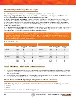
three circuits is less than the 40 amp branch circuit breaker limit of 225 feet (refer to
Table 3.3.1
), power distribution can
be accomplished through three 40 amp breakers with 30 mA ground-fault protection.
Figure 3.4.2: Expansion Joint
Kit Section
Figure 3.4.3: Detail at Steps
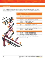
Figure 3.4.1: Junction
Box/Conduit
KSR™ Self-Regulating Heating Cable Layout:
When the location of the junction
boxes for power connections and end terminations has been established, lay out the
heating cable.
• Use a scaled drawing or sketch to simplify the process.
• Base layout on centre-to-centre spacing selected in Step 1.
• Do not exceed circuit lengths shown in
Table 3.3.1
.
•
Locate cable 2" to 4" below finished concrete surface.
Example: Heat Tracing for Building Entry
•
For standard slab (4" to 6" thick), place KSR™ Self-Regulating Heating Cable directly on top of reinforcing steel.
•
Attach to steel with nylon tie wraps on 24" (minimum) intervals.
Summary of Contents for TTS-5-1-OJ
Page 7: ...To use the 3M Heat Trace Bill of Materials Tool visit 3M ca HeatTrace 7 2 2 2 2 2 3 3 3 3...
Page 8: ...To use the 3M Heat Trace Bill of Materials Tool visit 3M ca HeatTrace 8 Pipe Freeze Protection...
Page 11: ...To use the 3M Heat Trace Bill of Materials Tool visit 3M ca HeatTrace 11 4 5 6 7 9 1 8 3 2...

