background image

Note:

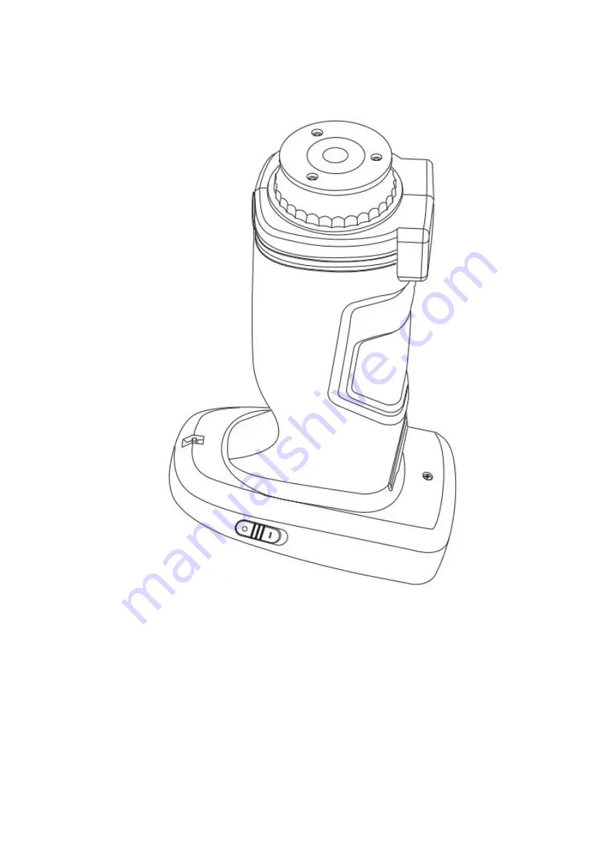
Please confirm the system measurement aperture should be the same with the actual aperture. If it is

Φ4mm aperture, switch to SAV; if Φ8mm aperture, switch to MAV, or it could cause wrong test result. After
switching the measurement aperture, you have to re-calibrate the instrument

Figure 49 Measurement Aperture

3.8.3 Bluetooth

The Bluetooth® that some models have is 4.0 Mode, which can connect PC with software.

When Bluetooth® is on, the icon will be displayed on the screen. After installing PC software in the computer, turn
on the Bluetooth ® in the instrument system setting, and start to pair the Bluetooth with the PC software. If
Bluetooth matching successes, it could measure the sample and standard or analyze the data on the computer.

3.8.4 Buzzer

Click “Buzzer” in “Settings”. When click “On”, there is a voice when measuring or there is no voice when
measuring.

Summary of Contents for TS Series

Page 1: ...Spectrophotometer OPERATION MANUAL Please read this manual carefully before use the spectrophotometer...

Page 2: ...and the instrument cannot be used again 5 For the first three times of charging it is better to get fully charged and then use it out before next charging External power 1 When external power supply i...

Page 3: ...Search Record 26 3 1 4 Standard Input 28 3 2 Calibration 30 3 4 Illuminant 30 3 4 Average 32 3 5 Color Space 32 3 6 Set Color Index 33 3 6 1 Set Color Index 33 3 6 2 36 3 7 Display Setting 40 3 8 Sys...

Page 4: ...ety of color spaces Cautions The spectrophotometer is a precise measuring instrument Please avoid drastic changes of external environment when measuring These changes including the flash of surroundin...

Page 5: ...rement 4 Aperture switch used for changing the measuring aperture setting this switch to MAV turn to 8mm aperture while setting this switch to SAV turn to 4mm aperture 5 Indicator light LED has green...

Page 6: ...ty White board is used for white calibration and black cavity is used for black calibration Please refer to the black and white correction section for details 2 Operating Instruction 2 1 Power On Off...

Page 7: ...n is valid or not and the remaining time if it is valid Figure 3 White and Black Calibration Click to continue and enter Black Calibration as shown in Figure 4 Fit the measuring port to the black cavi...

Page 8: ...as shown in Figure 5 According to the prompt confirm the serial number of white calibration plate correspond to the instrument and correct aperture setting then put the measuring aperture on white boa...

Page 9: ...the corresponding shortcut key to quickly switch the test data The middle part of the measurement interface is the data display area The instrument displays the corresponding chromaticity data accordi...

Page 10: ...Figure 6 Standard Measurement Interface...

Page 11: ...u interface as required please refer to Chapter 3 for details and the system default setting is CIE lab color space E ab color formula and the color index is empty If it is not currently in the measur...

Page 12: ...odel is I E while the default sample measurement is SCI 6 Illuminant Click it to quickly switch different light source among the D 6 5 A C F1 F12 etc 7 Color space Click it to quickly switch different...

Page 13: ...Figure 9 Standard measurement...

Page 14: ...standard 3 Sample Name Display the current measurement sample name and click it to quickly modify or the default is No name 4 Display mode Click SCI SCE to refresh the current measurement data in rea...

Page 15: ...9 Wavelength switch button As shown in Figure 12 click or the wave length and reflectance of the current sample will switch as range of 10nm interval Figure 11 Sample Measurement...

Page 16: ...on average after the set number of measurement Figure13 Average Measurement 2 5 Connecting to PC The instrument has a PC software with powerful extended function and it could realize more chromatic d...

Page 17: ...on the computer If the connection is successful the instrument can be fully controlled by software and relevant samples can be tested and analyzed 2 6 Print Micro Printer is an optional accessory and...

Page 18: ...s to enter the main menu and set all system functions from each submenu 3 1 Data Management Click Data Manage in main menu to enter data management interface as shown in Figure 16 Data management is m...

Page 19: ...1 Check Record 1 Check Standard Record Select Check Record to enter Standard Record interface as shown in Figure 17 The measurement condition shows the standard light mode UV status and the measureme...

Page 20: ...Figure 17 Standard Record...

Page 21: ...9 and click to confirm or to cancel delete back to operate menu Print Data Click Print data to print the current record data through micro printer Standard entering Click Standard entering to set the...

Page 22: ...Figure 21 Edit Name...

Page 23: ...Figure 21 Standard Entering 2 Check Sample Record Click in standard record interface to check the sample record as shown in Figure 22 Figure 22 Sample Record...

Page 24: ...tion Standard Input Click Standard Input to set the viewed sample record as the new current standard and then click Sample Measurement to perform sample measurement under this setting standard 3 1 2 D...

Page 25: ...Figure 24 Delete Record...

Page 26: ...re 26 Search Record Search Standard Name Click Search Standard Name to pop up to input search name interface as shown in Figure 27 Input searched name or contained character then click to confirm the...

Page 27: ...Figure 27 Input Search Name...

Page 28: ...Figure 28 Search Record Figure 29 Tips for no records 3 1 4 Standard Input In the data management interface click Standard Input to enter the standard input interface as shown in Figure 30...

Page 29: ...rm After all the information of the standard are finished and click OK the standard will be stored in the standard record list and its serial number will be accumulated in turn Note The manual input o...

Page 30: ...ibrate if the calibration time is more than 24 hours from last successful calibration 25 Black and white board is required to be cleaned regularly and kept in dark dustproof and dry conditions For bla...

Page 31: ...andard Click Illuminant as shown in Figure 33 users could select D65 A C D50 D55 D75 F1 F2 CWF F3 F4 F5 F6 F7 DLF F8 F9 F10 TPL5 F11 TL84 F12 TL83 U30 Click UV illuminant to select the UV light source...

Page 32: ...ieve 2 99 times average measurement In the main menu click Average input average times and click to confirm If input 1 time it measures as usual if more than 1 it will generate measurement results aft...

Page 33: ...olor Index interface could select the current color formula and color index as well as set the parameter of color formula and metameric index as shown in Figure 35 3 6 1 Set Color Index In the main me...

Page 34: ...Figure 35 Color Index...

Page 35: ...o calculate the color difference during sample measurement as shown in Figure 37 Figure 37 Color Formula E00 The selected color index will display the color index on standard measurement or sample mea...

Page 36: ...Figure 38 Yellowness Index 3 6 2 Parameter Factors Settings and Metameric Index In the color index interface click Parameter factors settings as shown in Figure 39...

Page 37: ...ure 39 Parameter Factors Setting 1 Setting Factors For C I E D E 2000 E00 C I E D E 1994 E 94 C M C E C M C l C users can set L C H value CMC only sets L and C Take E 94 for example as shown in Figure...

Page 38: ...Figure 40 E 94 Factors Click KL KC KH to enter edit interface as shown in Figure 41 input a value to click to confirm or to cancel...

Page 39: ...Figure 41 Factor KL 2 Metameric Index In the Parameter factors settings interface click Metameric Index as shown in Figure 42 separately set light 1 and light 2 and click to confirm or to cancel...

Page 40: ...bit If turn on the function of color offset it will display the color offset on the sample measurement as shown in Figure 44 if turn off it won t display color offset If turn on the function of test r...

Page 41: ...Figure 43 Display...

Page 42: ...System Settings include automatic measurement save measurement aperture Bluetooth buzzer measurement mode calibration valid measurement control mode language time screen backlight time screen backligh...

Page 43: ...Figure 46 System Settings...

Page 44: ...hown in Figure 49 counterclockwise rotates the measurement aperture and take off it then install the new aperture clockwise When there is a voice it means that the measuring aperture and the integrati...

Page 45: ...The Bluetooth that some models have is 4 0 Mode which can connect PC with software When Bluetooth is on the icon will be displayed on the screen After installing PC software in the computer turn on th...

Page 46: ...or I E I E is SCI SCE modes Single SCI or SCE mode test time is about 1 5 seconds and both SCI SCE test time is about 3 2 seconds 3 8 6 Calibration Validity White and black calibration as the benchmar...

Page 47: ...8 hours If Expired it would be only able to check records and not complete the test Until re calibrate it the calibration is valid If 24 Hours validity is selected the validity of Calibration will exp...

Page 48: ...to complete the test and upload data to PC software This mode is the default setting for the instrument Note The control mode is only valid when connecting to the PC software If unconnected it is only...

Page 49: ...g mode 5 minutes 10 minutes 30 minutes is the same setting as above When the screen is disappear it is able to short press the key to light up the screen and if the instrument is soft shut it is able...

Page 50: ...Setting in Settings as shown in Figure 54 Click the instrument will restore factory settings and all records will be cleared while click to cancel this operation Note Restore factory setting will dele...

Page 51: ...soiling the working surface with dirt and avoid exposing the White board under strong light Regularly clean the whiteboard working surface with a cloth and alcohol When calibrating clean the dust on t...

Page 52: ...can store more than 30000 pieces of test data 11 2 10 standard observer s angle multiple light source modes multiple surface color systems meet various standards of chromaticity indicators and the nee...

Page 53: ...S FAIL Result Color Offset Measuring Time About 1 5s Measure SCI SCE about 3 2s Repeatability Spectral reflectance MAV SCI Standard deviation within 0 08 400 nm to 700 nm within 0 18 Spectral reflecta...

Page 54: ...he specifications are subject to change without notice Appendix 1 Color There are three elements to observing color lighting source object and observer Changes in any of these three will affect the co...

Page 55: ...tablished by Judd Hunter The color difference of a color is called NBS color difference unit when the absolute value is 1 The new color difference formulas developed later often consciously adjusted t...

Reviews: