background image

11 

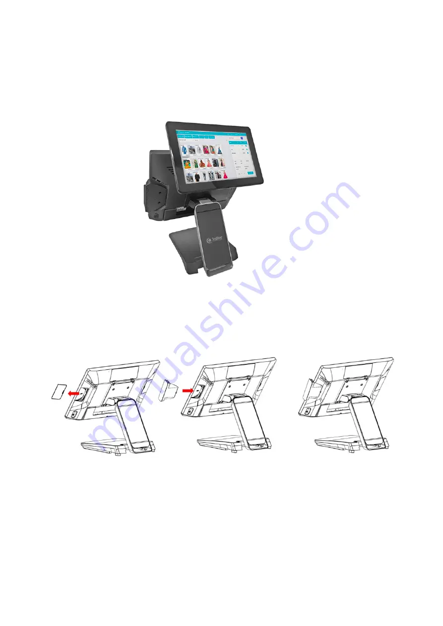
2. Install 2

nd 

display (integrated type) PTE0905-M10 on Smart DP

Remover Plastic Cover 

Plug in ID device (USB) and 

fix it via 1 x M3 screw 

Summary of Contents for PTE0905

Page 1: ...1 15 All In One POS System i5 9th Gen USER MANUAL PTE0905...

Page 2: ...idental tripping Do not twist pinch or clip the power cord 8 All cautions and warnings printed on the equipment should be followed 9 If the equipment is not used for a long time disconnect it from the...

Page 3: ...st 9 Chapter 2 Hardware Installation Setting 10 Optional Device Installation Customer Display Installation 10 Install Add on Device 11 Remove Install Cable Cover 11 Device status setting 12 Chapter 3...

Page 4: ...tu ur re es s Platform INTEL Coffee Lake platform support INTEL gen 9 processor Panel PC with Dual hinge stand Adjustable angle and height Improve the viewing angle enhance the user experience can als...

Page 5: ...TE E0 09 90 05 5 Wifi 802 11 a b g n ac Bluetooth 4 2 Optional 15 1024 x 768 P cap Touch Display Light Sensor Speaker Speaker LCM or 2nd 10 non touch LCD Smart DP Side USB Power Button Power LED Off R...

Page 6: ...3 O Op pt ti io on na al l P Pe er ri ip ph he er ra al l P PT TE E0 09 90 05 5 PTE0905 M10...

Page 7: ...4 Wall Mount Bracket...

Page 8: ...5 C Ca ab bl le e M Ma an na ag ge em me en nt t P PT TE E0 09 90 05 5...

Page 9: ...6 A Ad dj ju us st ta ab bl le e A An ng gl le e P PT TE E0 09 90 05 5...

Page 10: ...7 D Di im me en ns si io on n P PT TE E0 09 90 05 5...

Page 11: ...HDMI x1 For 2nd HDMI Monitor PUSB 24V 24V Power USB Smart I O Including 5V 12V 24V BIOS select and USB 2 0 x 2 and Com port x 1 I O cables 20V in 20V DC in 130W Cash drawer 12V 24V adjust by bios USB...

Page 12: ...9 P Pa ac ck ki in ng g L Li is st t P PT TE E0 09 90 05 5 Standard Optional Peripherals 1 15 2 20V 130W Power Adaptor 3 AC Cord Cable 4 RJ 45 to D sub9 Convert Cable x1...

Page 13: ...er r 2 2 H Ha ar rd dw wa ar re e I In ns st ta al ll la at ti io on n S Se et tt ti in ng g Optional Device Installation 1 Customer Display Installation Install Pull up the connector Fasten 2 screws...

Page 14: ...11 2 Install 2nd display integrated type PTE0905 M10 on Smart DP Remover Plastic Cover Plug in ID device USB and fix it via 1 x M3 screw...

Page 15: ...12 2 Remove Install Cable Cover Remove Cable Cover Install Cable Cover Device status setting...

Page 16: ...r ri iv ve er r U Ut ti il li it ty y I In ns st ta al ll la at ti io on n a an nd d S Se et tu up p 1 Chipset Locate chipset folder and double click on SetupChipset Click Next Click Accept Click Inst...

Page 17: ...14 2 Audio Double click Setup Click Yes Click Next Click Yes I want to restart my computer now Finish...

Page 18: ...15 3 Graphics Double Click igxpin Click Yes Click Next Click Next Click Finish...

Page 19: ...16 4 Intel ME Double Click SetupME Click Next Accept Terms then click Next Click Next Click Yes Click Finish...

Page 20: ...17 5 Serial IO Double Click SetupSerialIO Click Next Accept terms then click Next Click Next Click Next Select Yes I want to restart this computer now the click Finish...

Page 21: ...18 6 Sensor Double Click install Click Yes Press any key to continue 7 OPOS Please contact customer service to request OPOS Driver for 3nStar CashDrawer VFD LCM...

Page 22: ...2 Support 2666 MHz max 64G M 2 storage M 2 2280 slot x 1 Interface SATA 3 Support PCIE optional for 2nd M 2 Default I O Video Ports HDMI x1 PUSB 24V 24V Power USB SMART I O Including 5V 12V 24V BIOS s...

Page 23: ...RA9000XC4441 2 24V Printer Y cable Printer TC connector 3 pin hoshiden USB B RA9000XC4390 3 COM cable Com port device TC connector DB 9 RA9000XC4391 4 USB cable Payment device power TC connector 12V...

Reviews: