background image

User manual

11

5.5 Advanced Config

5.5.1 VLAN Config

The System VLAN function consist of two parts: one is VLAN configuration, which mainly include creating
VLAN, add VLAN membership; the other is VLAN property, the user can define PVID for every ports.

5.5.1.1 VLAN Configuration

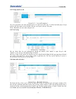
Picture 5.5.1.1 Vlan Configuration

The Switch allows users to create/delete VLAN, users can elect a port to associate with the VLAN
membership. The default VLAN is “VLAN 1”, it’s the management VLAN, all switch ports are defaulted in
this VLAN. Refer to Picture 5.1.1, users can create a new VLAN(called VLAN 2), and add port 1~4 to this
new VLAN.

5.5.1.2 VLAN Attributes

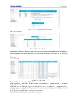
Please configure default VLAN ID(PVID). PVID can be renamed according to Port VLAN ID when connect
PDs to the switch, but the PVID will be defaulted as “1” when the port is used to uplink or downlink to
another switch.Please refer to the below picture.

Picture 5.1.2 VLAN Attributes

Summary of Contents for ES5018

Page 1: ...User manual 1 ES5018 Gigabit Managed POE Switch User manual Version 1 0 0 September 2014 www 3onedata com ...

Page 2: ...manual belong to their respective manufacturers Agreement As the product version upgrades or other reasons this document is subject to change without notice Unless other agreement this document only as a guide to use All statement information and suggestion in this document without warranty of any kind either expressed or implied Revision History Version No Date Reason V1 0 0 2014 9 Creating Docum...

Page 3: ...tics 9 Picture 5 3 2 1 Port Statistics 9 5 4 BASIC CONFIGURATION 9 5 4 1 IP Config 9 5 4 2 Management Account 10 5 4 3 Port Config 10 5 4 4 Bandwidth Allocation 10 5 5 ADVANCED CONFIG 11 5 5 1 VLAN Config 11 5 5 1 1 VLAN Configuration 11 5 5 1 2 VLAN Attributes 11 5 5 2 Port Trunk 12 5 5 3 Port Isolation 12 5 5 4 Loop Protection 13 5 5 5 PoE Config 13 5 6 NETWORK SECURITY 14 5 6 1 MAC Addresses 14...

Page 4: ...Ethernet cable from the switch end as adopting PoE All ports of ES5018 PoE Switch are auto sensing that make each port only provide power as detecting the presence of 802 3af at PoE supported devices 1 2 Features Compatible with both IEEE802 3at 30W and IEEE802 3af 15 4W can supply power to PDs under these two standards Automatically detect and supply power to IEEE802 3at and IEEE 802 3af complian...

Page 5: ...ase FX SFP port 7 Power input socket and switch 2 2 Power supply input ES5018 provides three power socket rear panel Used in the AC power input 220 VAC 2 3 Toggle switch There is a toggle switch on the right side of front panel beside the SFP ports If sliding the toggle switch to the left S LED side The LED display the LINK state of the port if Sliding the toggle switch to the right P LED side The...

Page 6: ...se TX PIN define is as follows Information necessary to explain Note TX Transmitting data RX receiving data no use MDI straight through cable MDI X Cross over cable 1000SFP fiber port mini GBIC 1000BaseSFP fiber port adopts gigabit mini GBIC transmission can choice different SFP module according to different transfer distance Fiber interface must use for pair TX port is transmit side must connect ...

Page 7: ...e remove the power socket before cleaning the switch Don wipe the switch with wet cloth or wash the switch with liquid 2 Don t stock the device in damp environment or near water to avoid water or moisture penetrating into the inner device 3 Don t put the device on a unstable box or desk the device will get damaged from falling 4 Please keep good ventilation indoor and make sure the heat dissipatio...

Page 8: ... switch 2 Connect the power cord and grounded cord 2 1 Select of AC Power Socket The neutral one phase 3 wire power socket is advised to adopt or the multifunctional PC power socket The neutral point of power supply must be well grounded please check the grounded power supply before operation 2 2 Connection of AC power cord Step one please connect one end of power cord to the power jack on the swi...

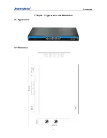
Page 9: ...User manual 6 Chapter 3 Appearance and Dimension 3 1 Appearance 3 2 Dimension ...

Page 10: ...accessories by your first using Please inform us or our distributor if your equipments have been damaged or lost any accessories we will try our best to satisfy you Description Quantity POE switch 1 Power Cord 1 User manual 1 CD 1 Warranty card 1 Product Qualified Card 1 ...

Page 11: ...password in the above login page the default password is admin The system only support single user login other logins will be refused until the user logs out If IP address conflict occurs it suggests the latest user didn t log out successfully Please reboot the device or try to log in again180s later It is advised to reset the IP address and password in first login and make sure the switch is not ...

Page 12: ...rect packets and quantity of forwarded received wrong packets If there are too many wrong packets it suggests the port has a poor working performance users need to examine the connection network cable or the network card There is data reset button you can clear the old data and start to get new data This software version doesn t support real time data refresh to get new data please click the refre...

Page 13: ...e are 5 types of port modes for choosing they are 10Harf 10Full 100Harf 100Full auto negotiation Default port mode is auto negotiation please change modes in pull down list The flow control function of system is closed in default resetting open it when needed 5 4 4 Bandwidth Allocation Picture 5 4 4 1 Bandwidth Allocation The Bandwidth Page allows user to define the bandwidth settings for specifie...

Page 14: ... users can elect a port to associate with the VLAN membership The default VLAN is VLAN 1 it s the management VLAN all switch ports are defaulted in this VLAN Refer to Picture 5 1 1 users can create a new VLAN called VLAN 2 and add port 1 4 to this new VLAN 5 5 1 2 VLAN Attributes Please configure default VLAN ID PVID PVID can be renamed according to Port VLAN ID when connect PDs to the switch but ...

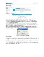
Page 15: ...ement There is pull down list in the port aggregation page there are two aggregation groups in the list each group supports maximum 4 ports If the user configure more than 4 ports for a group there will be a error prompt box displayed as below picture Picture 5 5 2 2 Port Trunk Error Prompt Box 5 5 3 Port Isolation One of the routine method to isolate L2 Messages is associating different ports to ...

Page 16: ...ig Picture5 5 5 1 PoE Config This page allows users to configure PoE features Enable Bar users can select from Enable or Disable in the Enable list if Disable selected the PoE power supply will be cut off Priority Bar users can select from Priority List three priority levels Low Middle High specific ports can be configured as power supply priorities The priority ports can get normal power supply w...

Page 17: ...here The MAC addresses can be dynamically learned or statically configured users can configure the MAC address mode And the dynamical learning of MAC addresses can be limited users can configure the quantity of port learning MAC addresses 5 6 1 1 MAC Dynamic Learning Picture5 6 1 1 MAC Dynamic Learning This page enables to check MAC address information dynamic MAC address list users can clear the ...

Page 18: ...control modes broadcast flow control multicast flow control unknown unicast flow control and unknown multicast flow control The will be impact on network system if there are too many packets the storm control function will help to suppress the storm problem 5 7 System Maintenance 5 7 1 Software Upgrade Picture 7 1 1 Software Upgrade Users can upgrade the switch software version in this page the cu...

Page 19: ... disconnect the two ports After factory reset please login the management system again The login process is the same with first login 5 7 3 Config Management Picture 5 7 3 1 Config Management This management page enables configure the saving uploading and downloading of data users can backup and recover the system configuration in this page Notes 1 Please save the configurations or the data will b...

Page 20: ...w port There is no data transmitting from PD and the switch can t learn a new address to do communication Waiting for 120s the swith will get auto updated address or transmitting data from the PD the switch will get address then All the ACT LEDs flash and the network rate slow down Caused by broadcast storm 1 Check if there is a loop problem reasonably configure the network 2 Check if there are la...

Reviews: