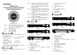
13. Grounding screw
14. Gigabit SFP
【
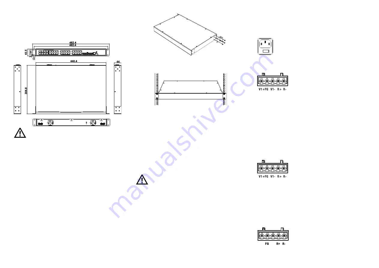
Mounting Dimension
】
Unit: mm
Notice Before Mounting:
Don't place or install the device in area near water or
moist, keep the relative humidity of the device
surrounding between 5%~95% without condensation.
Before power on, first confirm the supported power
supply specification to avoid over-voltage damaging
the device.
The device surface temperature is high after running;
please don't directly contact to avoid scalding.
【
Rack-mounted
】
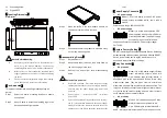
This product adopts rack-mounting, mounting steps as
below:
Step 1
Select the device mounting location to ensure
enough size.
Step 2
Adopt 4 bolts to install the mounting lugs in the
device position as figure below.
Step 3
Place the device in the rack; adopt 4 bolts to fix
two sides mounting lugs in the rack.
Step 4
Check and confirm the product is mounted firmly
on the rack, mounting ends.
【
Disassembling Device
】
Step 1
Device power off.
Step 2
Adopt screw driver to loosen the 4 bolts fixed on
the mounting lugs in the rack.
Step 3
Shift out the device from rack, disassembling
ends.
Notice before power on:
Power ON operation: First insert the power supply
terminal block into the device power supply interface,
and then plug the power supply plug contact and
power on.
Power switch “—” means power ON, “O” means
power OFF.
Power OFF operation: First, put the powers switch to
the "O" side and then disconnect the power supply.
Finally disconnect the connector between the device
and the power cord. Please notice the operation order
above.
【
Power Supply Connection
】
AC power supply
Model I, III of this device provide 2 AC power
supply access interfaces which come with a
switch.
Power supply range: 100~240VAC/DC.
DC power supply
Model II, IV of this device provide 2 DC
power supplies which are 5-pin 5.08mm
pitch terminal blocks. The power supply
occupies 3 pins on the left side and
supports anti-reverse connection. Power supply range:
36~72VDC
【
Restore Factory Settings
】
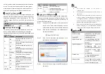
RESET is restoring default settings button. Device Restoring
default settings steps as follows: press and hold the RESET
button, power on the device again, wait for about 3~4
seconds to restore the factory settings.
【
Relay Connection
】
DC products
Model II, IV of this device support 2 relay
alarm information outputs which are
5-pin 5.08mm pitch terminal blocks. It
occupies 2 pins on the right side and R+ and R- are relay
alarm output parts. They are open circuit in normal non
alarm state, closed when any alarm information occurs. The
relay can externally connect to alarm lights or alarm buzzer
or other switching value collecting device in order to timely
notify operators when the alarm occurs.
AC products
Model I, III of this device support 2 relay
alarm information outputs which are
5-pin 5.08mm pitch terminal blocks. R+
and R- are relay alarm output parts. They are open circuit in

