background image

                                                                   User Manual 

3onedata proprietary and confidential 

Copyright © 3onedata Co., Ltd. 

117 

6.2.1  VLAN 

Function Description 

On the "Vlan-config" page, user can create VLAN and edit VLAN description. 

Operation Path 

Open in order: "Layer 2 Configuration > VLAN Configuration > Vlan-config". 

Interface Description 

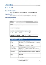
Vlan configuration interface as follows: 


The main element configuration description of Vlan configuration interface. 

Interface Element 

Description 

Add 

Click "Add" to add VLAN entry. 

Delete 

Check VLAN entry and click “delete” button to delete VLAN 
entry. 

VLAN 

VLAN ID number, value range is 1-4094. 

Description 

VLAN ID description, maximum 16 characters. 

Untagged Port 

Untagged port member to conduct untagged process to 
sending data frame. 

Tagged Port 

Tag port member to conduct tagged process to sending data 
frame. 

Status 

Status type: 


Static; 


Dynamic. 


Summary of Contents for IES6306 Series

Page 1: ...IES6306 Series Industrial Ethernet Switch User Manual Document Version 01 Issue Date 11 22 2021 Industrial Ethernet communication solution experts 3onedata Co Ltd ...

Page 2: ...d product service or features should be constrained by 3onedata commercial contracts and clauses The whole or part product service or features described in this document may beyond purchasing or using range 3onedata won t make any statement or warranty for this document content unless any other appointment exists Due to product version upgrading or other reason this document content will be upgrad...

Page 3: ...Zone 1 Baiwangxin High Technology Industrial park Nanshan District Shenzhen 518108 China Technology support tech support 3onedata com Service hotline 86 400 880 4496 E mail sales 3onedata com Fax 86 0755 26703485 Website http www 3onedata com ...

Page 4: ...tities of power supplies Audience This manual applies to the following engineers Network administrators Technical support engineers Hardware engineers Conventions Format Description Words with represent the interface words Fox example Port number Multiple paths are separated by the symbol Such as opening the local connection path description Open Control Panel Network Connection Local Area Connect...

Page 5: ...ury Warning Indicates a potentially hazardous situation which if not avoided could result in death or serious injury Note Calls attention to important information best practices and tips NOTE is used to address information not related to personal injury equipment damage and environment deterioration Key The tips of configuration and operation Tips Pay attention to the operation or information to e...

Page 6: ...2 1 3 CPU Load 7 2 2 IP 7 2 2 1 IP Configuration 7 2 2 2 IP Status Monitoring 11 2 3 NTP CONFIGURATION 13 2 3 1 NTP Client Configuration 13 2 3 2 NTP Server Configuration 14 2 4 TIME ZONE CONFIGURATION 14 2 5 SYSTEM LOG 15 2 5 1 Log Configuration 15 2 5 2 System Information 15 2 5 3 Alert Log 17 3 PORT 19 3 1 PORT 19 3 1 1 Port Settings 19 3 1 2 Port Status 21 3 1 3 Port Statistics Overview 22 3 1...

Page 7: ...ration 47 4 7 7 Access Configuration 48 4 8 RMON 49 4 8 1 Statistical Group Configuration 49 4 8 2 History Configuration 50 4 8 3 Alarm configuration 50 4 8 4 Link Event Configuration 52 4 8 5 Statistics Monitoring 53 4 8 6 History Monitoring 55 4 8 7 Alarm Monitoring 57 4 8 8 Event Monitoring 59 5 SECURE NETWORK 61 5 1 PORT LIMIT CONTROL 61 5 1 1 System Configuration 62 5 1 2 Port Configuration 6...

Page 8: ...2 Access 118 6 2 3 Trunk 119 6 2 4 Hybrid 120 6 3 DHCP SERVER 123 6 3 1 Mode Setting 123 6 3 2 Reserve IP configuration 124 6 3 3 DHCP Pool Configuration 125 6 3 4 Statistics Monitoring 130 6 3 5 Binding Monitoring 132 6 3 6 Conflict Monitoring 133 6 4 DHCP RELAY 133 6 4 1 Relay Configuration 133 6 4 2 Relay Statistics Monitoring 135 6 5 DHCP SNOOPING 137 6 5 1 Listening Configuration 137 6 5 2 Li...

Page 9: ...atistics Monitoring 167 6 13 RING 168 6 13 1 Ring Configuration 168 6 13 2 Loop Monitoring 170 6 14 MEP 171 6 14 1 Maintenance Entity Point 171 6 14 2 MEP Configuration 172 6 15 ERPS 196 6 15 1 ERPS 196 6 15 2 ERPS Configuration 198 7 MULTICAST 205 7 1 IGMP SNOOPING 205 7 1 1 Basic Configuration 205 7 1 2 VLAN Configuration 206 7 1 3 Status Monitoring 208 7 1 4 Group Information Monitoring 209 7 1...

Page 10: ...P CLASSIFICATION 234 9 11 QOS CONTROL LIST CONFIGURATION 235 9 12 QOS STATISTICS 237 9 13 QCL STATUS 238 10 SYSTEM DIAGNOSIS 240 10 1 MIRRORING 240 10 2 PING 241 10 3 CABLE DETECTION 242 11 SYSTEM MAINTENANCE 245 11 1 RESTART DEVICE 245 11 2 FACTORY DEFAULTS 245 11 3 SOFTWARE UPLOAD 246 11 4 FIRMWARE SELECTION 246 12 SYSTEM CONFIGURATION 248 12 1 SAVE STARTUP CONFIG 248 12 2 DOWNLOAD 248 12 3 UPLO...

Page 11: ...Operating system Windows XP Windows 7 1 2 Setting IP Address of PC The switch default management as follows IP Settings Default Value IP Address 192 168 1 254 Subnet mask 255 255 255 0 When configuring a switch through the Web Before making remote configuration make sure that the route between the computer and the switch is reachable Before local configuration please make sure the IP address of th...

Page 12: ...en Control panel Network connection Local area connection Properties Internet protocol version TCP IPv4 Properties Step 2 Change the 5 selected by the red frame in the figure to 1 Step 3 Click OK Step 4 End Notice In windows system if user adopts the advanced configuration function of IP address and accesses the switch device via setting IP dummy address the following two managed functions can t b...

Page 13: ...orts one default user This user has administrator privilege and can configure devices via WEB TELNET SSH CLI etc The default username and password are admin please strictly distinguish capital and small letter while entering If you log in to the device for the first time you will be prompted to change the default user s initial password If the password has been modified through the WEB or CLI the ...

Page 14: ...n or equal to 8 and be composed of two or more of uppercase letters lowercase letters numbers and special characters After changing the password save the current configuration on the System Configuration Save startup config page to take effect Click OK Pop up a window as the figure below enter the user name and password on the login window Click the login button End After login in successfully use...

Page 15: ... to 126 System Name An administratively assigned name for this managed node By convention this is the node s fully qualified domain name A domain name is a text string drawn from the alphabet A Za z digits 09 minus sign No space characters are permitted as part of a name The first character must be an alpha character And the first or last character must not be a minus sign The allowed string lengt...

Page 16: ...ystem name configured by the path System System Information Configuration Information System Name Position The location configured in System System Information Configuration Information System Location MAC Address The MAC Address of this switch System Date The current GMT system time and date The system time is obtained through the Timing server running on the switch if any System Uptime The perio...

Page 17: ...econds intervals The last 120 samples are graphed and the last numbers are displayed as text as well In order to display the SVG graph your browser must support the SVG format Consult the SVG Wiki for more information on browser support Specifically at the time of writing Microsoft Internet Explorer will need to have a plugin installed to support SVG Buttons Auto refresh Check this box to refresh ...

Page 18: ... In Router mode traffic is routed between all interfaces IP Interfaces Delete Select this option to delete an existing IP interface VLAN The VLAN associated with the IP interface Only ports in this VLAN will be able to access the IP interface This field is only available for input when creating a new interface IPv4 DHCP Enabled Enable the DHCPv4 client by checking this box If this option is enable...

Page 19: ... blank if IPv4 operation on the interface is not desired or no DHCP fallback address is desired IPv4 Mask Length The IPv4 network mask in number of bits prefix length Valid values are between 0 and 30 bits for a IPv4 address If DHCP is enabled this field configures the fallback address network mask The field may be left blank if IPv4 operation on the interface is not desired or no DHCP fallback ad...

Page 20: ... formed from an interface identifier based on the hardware address which is supposed to be uniquely assigned Once the DAD Duplicate Address Detection detects the address duplication the operation on the interface SHOULD be disabled At this moment manual intervention is required to resolve the address duplication For example check whether the loop occurs in the VLAN or there is indeed other device ...

Page 21: ...be effective only when the corresponding IPv6 interface is valid If the IPv6 gateway address is link local it must specify the next hop VLAN for the gateway If the IPv6 gateway address is not link local system ignores the next hop VLAN for the gateway Buttons Add new IP interface click here to add new IP interface A maximum of 8 interfaces is supported Add new IP route click to add new IP route A ...

Page 22: ...ype The address type of the entry This may be LINK or IPv4 Address The current address of the interface of the given type Status The status flags of the interface and or address IP Routes Network The destination IP network or host address of this route Gateway The gateway address of this route Status The status flags of the route ...

Page 23: ...Check this box to refresh the page automatically Automatic refresh occurs every 3 seconds 2 3 NTP Configuration 2 3 1 NTP Client Configuration Configure NTP on this page Mode Indicates the NTP mode operation Possible modes are Enabled Enable NTP client mode operation Disabled Disable NTP client mode operation Server Provide the IPv4 or IPv6 address of a NTP server IPv6 address is in 128 bit record...

Page 24: ...ting multiple 16 bit groups of contiguous zeros but it can appear only once It can also represent a legally valid IPv4 address For example 192 1 2 34 In addition it can also accept a domain name address 2 3 2 NTP Server Configuration Configure NTP server on this page Mode Configure the NTP server mode options are as follows Enable Enable NTP Server Disable Disable NTP Server 2 4 Time Zone Configur...

Page 25: ...ndicates the server mode operation When the mode operation is enabled the syslog message will send out to the syslog server The syslog protocol is based on UDP communication and received on UDP port 514 and the syslog server will not send acknowledgments back since UDP is a connectionless protocol and it does not provide acknowledgments The syslog packet will always send out even if the syslog ser...

Page 26: ...eb page will show the beginning entries of this table The Level input field is used to filter the display system log entries The Clear Level input field is used to specify which system log entries will be cleared To clear specific system log entries select the clear level first then click the button Delete The Start from ID input field allow the user to change the starting point in this table Clic...

Page 27: ...essage The detailed message of the system log entry Buttons Auto refresh Check this box to refresh the page automatically Automatic refresh occurs every 3 seconds Refresh Updates the table entries starting from the current entry Delete Refresh the selected entries Updates the table entries starting from the first available entry Updates the table entries ending at the last entry currently displaye...

Page 28: ...nual 3onedata proprietary and confidential Copyright 3onedata Co Ltd 18 Level The severity level of the system log entry ID The ID 1 of the system log entry Message The detailed message of the system log entry ...

Page 29: ...k Status The current link state is displayed graphically Green indicates the link is up and red that it is down Current Link Speed Current speed duplexes the current link speed of this port Configured Link Speed Selects any available link speed for the given switch port Only speeds supported by the specific port is shown Possible speeds are Disable Disable the switch port Auto Port auto negotiatin...

Page 30: ... is Autonegotiation the port will only advertise the specified duplex as either Fdx or Hdx to the link partner By default port will advertise all the supported duplexes if the Duplex is Auto Advertise Speed When Speed is set as auto that is Autonegotiation the port will only advertise the specified speeds 10M 100M 1G to the link partner By default port will advertise all the supported speeds if sp...

Page 31: ... If the EtherType Length field is above 1535 it indicates that the field is used as an EtherType indicating which protocol is encapsulated in the payload of the frame If frame length check is enabled frames with payload size less than 1536 bytes are dropped if the EtherType Length field doesn t match the actually payload length If frame length check is disabled frames are not dropped due to frame ...

Page 32: ... ports The displayed counters are Port The switch port number Note The description of the port Packets The number of received and transmitted packets per port Bytes The number of received and transmitted bytes per port Errors The number of frames received in error and the number of incomplete transmissions per port Drops The number of frames discarded due to ingress or egress congestion Filtered T...

Page 33: ...e error counters for receive and transmit Receive Total and Transmit Total Rx and Tx Packets The number of received and transmitted good and bad packets Rx and Tx Octets The number of received and transmitted good and bad bytes Includes FCS but excludes framing bits Rx and Tx Unicast The number of received and transmitted good and bad unicast packets Rx and Tx Multicast The number of received and ...

Page 34: ...ved with valid CRC Rx Oversize The number of long 2 frames received with valid CRC Rx Fragments The number of short 1 frames received with invalid CRC Rx Jabber The number of long 2 frames received with invalid CRC Rx Filtered The number of received frames filtered by the forwarding process 1 Short frames are frames that are smaller than 64 bytes 2 Long frames are frames that are longer than the c...

Page 35: ...1 DDMI Configuration This page allows for configuring DDMI Mode Indicates the DDMI mode operation Possible modes are Enabled Enable DDMI mode operation Disabled Disable DDMI mode operation Buttons Save Click to save changes Reset Click to undo any changes made locally and revert to previously saved values 3 2 2 DDMI Overview Monitor This page displays overview DDMI information Port DDMI port ...

Page 36: ...P vendor Serial Number Indicates Vendor SN Serial number provided by vendor Revision Indicates Vendor rev Revision level for part number provided by vendor Data Code Indicates Date code Vendor s manufacturing date code Transceiver Indicates Transceiver compatibility 3 3 Relay Alarm On the page of Relay user can enable power supply port alarm and configure relevant alarm information ...

Page 37: ...le Link Connection status of power supply the device will automatically recognize and display values include Fault Normal Port Mode Configuration Port Display port number of the device value range is 110 Mode Enable the port alarm or not options as follows Enable when the port is disconnected port alarm will be triggered Disable Link Connection status of the port the device will automatically reco...

Page 38: ... that is that is granted the fully control of the device However other values need to refer to the privilege level of each group User s privilege should be same or greater than the group privilege level to have the access of that group By default setting most groups privilege level 5 has the read only access and privilege level 10 has the read write access And the system maintenance software uploa...

Page 39: ...ach group privilege level User s privilege should be same or greater than the group privilege level to have the access of that group By default setting most groups privilege level 5 has the read only access and privilege level 10 has the read write access And the system maintenance software upload factory defaults and etc need user privilege level 15 Generally the privilege level 15 can be used fo...

Page 40: ...llowing description defines these privilege level groups in details System Contact Name Location Timezone Daylight Saving Time Log Security Authentication System Access Management Port contains Dot1x port MAC based and the MAC Address Limit ACL HTTPS SSH ARP Inspection IP source guard IP Everything except ping Port Everything except VeriPHY Diagnostic methods ping and VeriPHY Maintenance CLI Syste...

Page 41: ...istics read only status statistics read write for example for clearing of statistics User Privilege should be same or greater than the authorization Privilege level to have the access to that group 4 3 Auth method 4 3 1 Authentication Method Configuration This option allows you to configure how a user is authenticated when he logs into the switch via one of the management client interfaces The tab...

Page 42: ...ended to configure secondary authentication as local This will enable the management client to log in via the local user database if none of the configured authentication servers are alive 4 3 2 Command Authorization Method Configuration The command authorization section allows you to limit the CLI commands available to a user The table has one row for each client type and a number of columns whic...

Page 43: ...he configuration below applies Method Method can be set to one of the following values No Authentication is disabled tacacs Uses one or more of the remote TACACS servers for accounting Cmd Lvl Enable statistics of all commands with a privilege level higher than or equal to this level Valid values are in the range 0 to 15 Leave the field empty to disable command accounting Exec Enables exec login a...

Page 44: ...switch Mode Indicate the HTTPS mode operation Possible modes are Enabled Enable HTTPS mode operation Disabled Disable HTTPS mode operation Automatic Redirect Indicate the HTTPS redirect mode operation It is only significant when HTTPS Mode Enabled is selected When the redirect mode is enabled the HTTP connection will be redirected to HTTPS connection automatically Notice that the browser may not a...

Page 45: ... my cert my key my pem Notice that the RSA certificate is recommended since most of the new version of browsers has removed support for DSA in certificate e g Firefox v37 and Chrome v39 Possible methods are Web bowser Upload a certificate via Web browser URL Upload a certificate via URL the supported protocols are HTTP HTTPS TFTP and FTP The URL format is protocol username password host port path ...

Page 46: ...s is 16 If the type of the application matches any one of the access management entries it allows access to the switch Mode Indicates the access management mode operation Possible modes are Enabled Enables access management mode operation Disable Disable access management mode operation Delete Check the corresponding check box to delete an entry It will be deleted during the next Save operation VL...

Page 47: ...e IP address range provided in the entry Buttons Add new entry Click to add a new access management entry Save Click to save changes Undo Click to undo any changes made locally and revert to previously saved values 4 6 2 Access Management Statistics Monitoring This page provides statistics for access management Interface The interface type through which the remote host can access the switch Receiv...

Page 48: ...MP supported version Possible versions are SNMP v1 Sets SNMP supported version 1 SNMP v2c Sets SNMP supported version 2c SNMP v3 Set version 3 supported by SNMP Read Community Indicates the community read access string to permit access to SNMP agent The allowed string length is 1 to 255 and the allowed content is the ASCII characters from 33 to 126 The field is applicable only when SNMP version is...

Page 49: ...a particular range of source addresses can be used to restrict source subnet Engine ID Indicates the SNMPv3 engine ID The string must contain an even number in hexadecimal format with number of digits between 10 and 64 but all zeros and all F s are not allowed Change of the Engine ID will clear all original local users Buttons Save Click to save changes Undo Click to undo any changes made locally ...

Page 50: ...dot dash Spaces are not allowed the first character must be an alpha character and the first and last characters must not be a dot or a dash Indicates the SNMP trap destination IPv6 address IPv6 address is in 128 bit records represented as eight fields of up to four hexadecimal digits with a colon separating each field For example fe80 215 c5ff fe03 4dc7 The symbol is a special syntax that can be ...

Page 51: ...NMP mode operation Possible modes are Enabled Enable SNMP mode operation Disabled Disable SNMP mode operation Trap Version Indicates the SNMP supported version Possible versions are SNMP v1 Set SNMP supported version 1 SNMP v2c Set SNMP supported version 2c SNMP v3 Set version 3 supported by SNMP Trap Community Indicates the community access string when sending SNMP trap packet The allowed string ...

Page 52: ...tination port Indicates the SNMP trap destination port SNMP Agent will send SNMP message via this port the port range is 1 65535 Trap Inform Mode Indicates the SNMP trap inform mode operation Possible modes are Enabled Enable SNMP trap inform mode operation Disabled Disable SNMP trap inform mode operation Trap Inform Timeout seconds Indicates the SNMP trap inform timeout The allowed range is 0 to ...

Page 53: ...ce Indicates that the Interface group s traps Possible traps are Indicates that the SNMP entity is permitted to generate authentication failure traps Possible modes are Link Up Enable disable Link up trap Link Down Enable disable Link down trap LLDP Enable disable LLDP trap Authentication Indicates that the authentication group s traps Possible traps are SNMP Authentication Fail Enable disable SNM...

Page 54: ... community string Source IP Indicates the SNMP access source address A particular range of source addresses can be used to restrict source subnet when combined with source mask Source Mask Indicates the SNMP access source address mask Buttons Add new community entry Click to add a new community entry Save Click to save changes Undo Click to undo any changes made locally and revert to previously sa...

Page 55: ...d the allowed content is ASCII characters from 33 to 126 Security Level Indicates the security model that this entry should belong to Possible security models are NoAuth NoPriv No authentication and no encryption Auth NoPriv Authentication and no encryption Auth Priv Authentication and encryption The value of security level cannot be modified if entry already exists That means must first ensure th...

Page 56: ...2 and the allowed content is ASCII characters from 33 to 126 Buttons Add new user entry Click to add new entry Save Click to save changes Undo Click to undo any changes made locally and revert to previously saved values 4 7 5 Group Configuration This option allows you to configure the SNMPv3 group table The entry index keys are Security Model and Security Name Delete Check the corresponding check ...

Page 57: ...ration Configure SNMPv3 view table on this page The entry index keys are View Name and OID Subtree Delete Check to delete the entry It will be deleted during the next save View Name A string identifying the view name that this entry should belong to The allowed string length is 1 to 32 and the allowed content is ASCII characters from 33 to 126 View Type Indicates the view type that this entry shou...

Page 58: ...and Security Level Delete Check to delete the entry It will be deleted during the next save Group Name A string identifying the group name that this entry should belong to The allowed string length is 1 to 32 and the allowed content is ASCII characters from 33 to 126 Security Mode Indicates the security model that this entry should belong to Possible security models are any Any security model acce...

Page 59: ...k to add a new access entry Save Click to save changes Undo Click to undo any changes made locally and revert to previously saved values 4 8 RMON 4 8 1 Statistical Group Configuration Configure RMON Statistics table on this page The entry index key is ID Delete Check to delete the entry It will be deleted during the next save ID Indicates the index of the entry The range is from 1 to 65535 Data So...

Page 60: ...he port is switch 3 port 5 the value is 2000005 Interval Indicates the interval in seconds for sampling the history statistics data The range is from 1 to 3600 default value is 1800 seconds Buckets Indicates the maximum data entries associated this History control entry stored in RMON The range is from 1 to 3600 default value is 50 Buckets Granted The number of data shall be saved in the RMON Butt...

Page 61: ...e packets are normal InErrors The number of inbound packets that contained errors preventing them from being deliverable to a higher layer protocol InUnknownProtos the number of the inbound packets that were discarded because of the unknown or un support protocol OutOctets The number of octets transmitted out of the interface including framing characters OutUcastPkts The number of uni cast packets...

Page 62: ...t value is larger than the rising threshold or less than the falling threshold default Rising Threshold Rising threshold value 2147483648 2147483647 Rising Index Rising event index 165535 Falling Threshold Falling threshold value 2147483648 2147483647 Falling Index Falling event index 165535 Buttons Add new entry Click to add a new community entry Save Click to save changes Undo Click to undo any ...

Page 63: ...e changes Undo Click to undo any changes made locally and revert to previously saved values 4 8 5 Statistics Monitoring This page provides an overview of RMON Statistics entries Each page shows up to 99 entries from the Alarm table default being 20 selected through the entries per page input field When first visited the web page will show the first 20 entries from the beginning of the Alarm table ...

Page 64: ...rected to the broadcast address Multicast The total number of good packets received that were directed to a multicast address CRC Errors Total number of packets received Eight bit byte with length excluding the frame part but including FCS octets between 64 and 1518 but there is an integer FCS error bad frame check sequence FCS of eight bit byte or a bad FCS eight bit byte which is not an integer ...

Page 65: ...tets in length 512 1023 The total number of packets including bad packets received that were between 512 to 1023 octets in length 1024 1588 The total number of packets including bad packets received that were between 1024 to 1588 octets in length Buttons Auto refresh Check this box to refresh the page automatically Automatic refresh occurs every 3 seconds Refresh Click to refresh the page immediat...

Page 66: ...ed the text No other entries is shown in the displayed table Use the button to start over The displayed fields are History Index Indicates the index of History control entry Sample Index Indicates the index of the data entry associated with the control entry Sample Start The value of sysUpTime at the start of the interval over which this sample was measured Drop The total number of events in which...

Page 67: ... received with invalid CRC Coll The best estimate of the total number of collisions on this Ethernet segment Utilization The best estimate of the mean physical layer network utilization on this interface during this sampling interval in hundredths of a percent Buttons Auto refresh Check this box to refresh the page automatically Automatic refresh occurs every 3 seconds Refresh Click to refresh the...

Page 68: ...d is reached the text No more entries is shown in the displayed table Use the button to start over The displayed fields are ID Indicates the index of Alarm control entry Interval Indicates the interval in seconds for sampling and comparing the rising and falling threshold Variable Indicates the particular variable to be sampled Sample Type The method of sampling the selected variable and calculati...

Page 69: ...elected through the entries per page input field When first visited the web page will show the first 20 entries from the beginning of the Event table The first displayed will be the one with the lowest Event Index and Log Index found in the Event table The from event index and log index input field allows the user to select a starting point in the Event table Clicking the Refresh button will updat...

Page 70: ...uttons Auto refresh Check this box to refresh the page automatically Automatic refresh occurs every 3 seconds Refresh Click to refresh the page immediately Updates the table starting from the first entry in the Event Table i e the entry with the lowest Event Index and Log Index Updates the table starting with the entry after the last entry currently displayed ...

Page 71: ... port A user is identified by a MAC address and VLAN ID If Limit Control is enabled on a port the limit specifies the maximum number of users on the port If this number is exceeded an action is taken The action can be one of the four different actions as described below The Limit Control module utilizes a lower layer module Port Security module which manages MAC addresses learnt on the port The Li...

Page 72: ...owing scenario Suppose an end host is connected to a 3rd party switch or hub which in turn is connected to a port on this switch on which Limit Control is enabled The end host will be allowed to forward if the limit is not exceeded Now suppose that the end host logs off or powers down If it wasn t for aging the end host would still take up resources on this switch and will be allowed to forward To...

Page 73: ...be sent every time the limit gets exceeded Shutdown If Limit 1 MAC addresses is seen on the port shut down the port This implies that all secured MAC addresses will be removed from the port and no new address will be learned Even if the link is physically disconnected and reconnected on the port by disconnecting the cable the port will remain shut down There are three ways to re open the port 1 Bo...

Page 74: ...y Switch Status This page shows the Port Security status Port Security is a module with no direct configuration Configuration comes indirectly from other modules the user modules When a user module has enabled port security on a port the port is set up for software based learning In this mode frames from unknown MAC addresses are passed on to the port security module which in turn asks all user mo...

Page 75: ... has one row for each port on the switch and a number of columns which are Port The port number for which the status applies Click the port number to see the status for this particular port Users Each of the user modules has a column that shows whether that module has enabled Port Security or not A means that the corresponding user module is not enabled whereas a letter indicates that the user mod...

Page 76: ...espectively If no user modules are enabled on the port the Current column will show a dash If the Limit Control user module is not enabled on the port the Limit column will show a dash Buttons Auto refresh Check this box to refresh the page automatically Automatic refresh occurs every 3 seconds Refresh Click to refresh the page immediately 5 2 2 Port Monitoring This page shows the MAC addresses se...

Page 77: ...MAC address still forwards traffic If the age period measured in seconds expires and no frames have been seen the MAC address will be removed from the MAC table Otherwise a new age period will begin If aging is disabled or a user module has decided to hold the MAC address indefinitely a dash will be shown Buttons Use the port select box to select which port to show status for Auto refresh Check th...

Page 78: ...on his system The switch uses the user s MAC address to authenticate against the backend server Intruders can create counterfeit MAC addresses which makes MAC based authentication less secure than 802 1X authentication The NAS configuration consists of two sections a system and a port wide System Configuration Mode Indicates if NAS is globally enabled or disabled on the switch If globally disabled...

Page 79: ...the Port Security functionality to secure MAC addresses Single 802 1X Multi 802 1X MAC Based Auth When the NAS module uses the Port Security module to secure MAC addresses the Port Security module needs to check for activity on the MAC address in question at regular intervals and free resources if no activity is seen within a given period of time This parameter controls exactly this period and can...

Page 80: ...ally enable disable RADIUS server assigned QoS Class functionality When checked the individual ports ditto setting determine whether RADIUS assigned QoS Class is enabled on that port When unchecked RADIUS server assigned QoS Class is disabled on all ports RADIUS Assigned VLAN Enabled RADIUS assigned VLAN provides a means to centrally control the VLAN on which a successfully authenticated supplican...

Page 81: ...frame has been received on the port for the life time of the port Once the switch considers whether to enter the Guest VLAN it will first check if this option is enabled or disabled If disabled unchecked default the switch will only enter the Guest VLAN if an EAPOL frame has not been received on the port for the life time of the port If enabled checked the switch will consider entering the Guest V...

Page 82: ...lates the EAP part of the frame into the relevant type EAPOL or RADIUS and forwards it When authentication is complete the RADIUS server sends a special packet containing a success or failure indication Besides forwarding this decision to the supplicant the switch uses it to open up or block traffic on the switch port connected to the supplicant Note Suppose two backend servers are enabled and tha...

Page 83: ...02 1X based authentication is that the clients don t need special supplicant software to authenticate The disadvantage is that MAC addresses can be spoofed by malicious users equipment whose MAC address is a valid RADIUS user can be used by anyone Also only the MD5 Challenge method is supported The maximum number of clients that can be attached to a port can be limited using the Port Security Limi...

Page 84: ...hentication is in progress Buttons Refresh Click to refresh the page Save Click to save changes Undo Click to undo any changes made locally and revert to previously saved values 5 3 2 Network Access Server Switch Status This page provides an overview of the current NAS port states Port The switch port number Click to navigate to detailed NAS statistics for this port Admin State The port s current ...

Page 85: ...S assigned is appended to the VLAN ID Read more about RADIUS assigned VLANs here If the port is moved to the Guest VLAN Guest is appended to the VLAN ID Read more about Guest VLANs here Buttons Auto refresh Check this box to refresh the page automatically Automatic refresh occurs every 3 seconds Refresh Click to refresh the page immediately 5 3 3 NAS Statistics This page provides detailed NAS stat...

Page 86: ...d Permit or denied Deny The default value is Permit Rate Limiter ID Select which rate limiter to apply on this port The allowed values are Disabled or the values 1 through 16 The default value is Disabled EVC Policer Select whether EVC policer is enabled or disabled The default value is Disabled Note that ACL rate limiter and EVC policer can not both be enabled EVC Policer ID Select which EVC poli...

Page 87: ... Specify the port shut down operation of this port The allowed values are Enable If a frame is received on the port the port will be disabled Disabled Port shut down is disabled The default value is Disabled Note The shutdown feature only works when the packet length is less than 1518 without VLAN tags Status Specify the port state of this port The allowed values are Enabled To reopen ports by cha...

Page 88: ...e is 0 3276700pps or 0 100 200 300 1000000 in kbps Unit Specify the rate unit The allowed values are pps Packets per second kbps Kbits per second Buttons Save Click to save changes Undo Click to undo any changes made locally and revert to previously saved values 5 4 3 Access Control List Configuration This page shows the Access Control List ACL which is made up of the ACEs defined on this switch E...

Page 89: ...pe EType The ACE will match Ethernet Type frames Note that an Ethernet Type based ACE will not get matched by IP and ARP frames ARP The ACE will match ARP RARP frames IPv4 The ACE will match all IPv4 frames IPv4 ICMP ACE will match IPv4 frames with ICMP protocol IPv4 UDP ACE will match IPv4 frames with UDP protocol IPv4 TCP ACE will match IPv4 frames with TCP protocol IPv4 Other ACE will match IPv...

Page 90: ...s received on the port are not mirrored The default value is Disabled Counter The counter indicates the number of times the ACE was hit by a frame Modification Buttons You can modify each ACE Access Control Entry in the table using the following buttons Add Inserts a new ACE before the current row Edit Edits the ACE row Up Moves the ACE up the list down Moves the ACE down the list Delete Delete AC...

Page 91: ...that an Ethernet Type based ACE will not get matched by IP and ARP frames ARP The ACE will match ARP RARP frames IPv4 The ACE will match all IPv4 frames IPv4 ICMP ACE will match IPv4 frames with ICMP protocol IPv4 UDP ACE will match IPv4 frames with UDP protocol IPv4 TCP ACE will match IPv4 frames with TCP protocol IPv4 Other ACE will match IPv4 frames which are not ICMP UDP TCP IPv6 The ACE will ...

Page 92: ...CE The specific ACE is not applied to the hardware due to hardware limitations Buttons The select box determines which ACL user is affected by clicking the buttons Auto refresh Check this box to enable an automatic refresh Automatic refresh occurs every 3 seconds Refresh Click to refresh the page 5 5 RADIUS 5 5 1 RADIUS Server Configuration This page allows you to configure the RADIUS servers Glob...

Page 93: ...a value greater than 0 zero will enable this feature but only if more than one server has been configured Key The secret key up to 63 characters long shared between the RADIUS server and the switch NAS IP Address Attribute 4 The IPv4 address to be used as attribute 4 in RADIUS Access Request packets If this field is left blank the IP address of the outgoing interface is used NAS IPv6 Address Attri...

Page 94: ... the global retransmit value Leaving it blank will use the global retransmit value Key This optional setting overrides the global key Leaving it blank will use the global key Adding a New Server Add new server Click to add a new RADIUS server An empty row is added to the table and the RADIUS server can be configured as needed Up to 5 servers are supported Delete The button can be used to undo the ...

Page 95: ...n the dead time expires The number of seconds left before this occurs is displayed in parentheses This state is only reachable when more than one server is enabled Accounting Port Billing UDP port number Accounting Status The current status of the server This field takes one of the following values Disabled The server is disabled Not Ready The server is enabled but IP communication is not yet up a...

Page 96: ... Authentication Client MIB Use the server select box to switch between the backend servers to show details for Packet Counters RADIUS authentication server packet counter There are seven receive and four transmit counters Direction Name RFC4668 Name Description Received Access Accepts radiusAuth ClientExtA ccessAcce pts The number of RADIUS Access Accept packets valid or invalid received from the ...

Page 97: ...icators radiusAuth ClientExtB adAuthenti cators The number of RADIUS Access Response packets containing invalid authenticators or Message Authenticator attributes received from the server Received Unknown Types radiusAuth ClientExtU nknownTy pes The number of RADIUS packets that were received with unknown types from the server on the authentication port and dropped Received Packets Dropped radiusA...

Page 98: ...retransmission Transmitted Timeouts radiusAuth ClientExtTi meouts The number of authentication timeouts to the server After a timeout the client may retry to the same server send to a different server or give up A retry to the same server is counted as a retransmit as well as a timeout A send to a different server is counted as a Request as well as a timeout Other Info This section contains inform...

Page 99: ...nd Trip Time radiusAuthClientExtR oundTripTime The time interval measured in milliseconds between the most recent Access Reply Access Challenge and the Access Request that matched it from the RADIUS authentication server The granularity of this measurement is 100 ms A value of 0 ms indicates that there hasn t been round trip communication with the server yet RADIUS Accounting Statistics The statis...

Page 100: ... on the accounting port Received Packets Dropped radiusAccClient ExtPacketsDrop ped The number of RADIUS packets that were received from the server on the accounting port and dropped for some other reason Transmitt ed Requests radiusAccClient ExtRequests The number of RADIUS packets sent to the server This does not include retransmissions Transmitt ed Retransmissions radiusAccClient ExtRetransmiss...

Page 101: ... port for the accounting server in question Status Shows the state of the server It takes one of the following values Disabled The selected server is disabled Not Ready The server is enabled but IP communication is not yet up and running Ready The server is enabled IP communication is up and running and the RADIUS module is ready to accept accounting attempts Dead X seconds left Accounting attempt...

Page 102: ...mines which server is affected by clicking the buttons Auto refresh Check this box to enable an automatic refresh Automatic refresh occurs every 3 seconds Refresh Click to refresh the page immediately Clear Clears the counters for the selected server The Pending Requests counter will not be cleared by this operation 5 6 Ethernet Services 5 6 1 Port Configuration This page displays current EVC port...

Page 103: ...inner tag identifying the EVC The allowed values are Inner Enable inner tag in EVC classification Outer Enable outer tag in EVC classification Address Mode The IP MAC address mode specifying whether the EVC classification must be based on source SMAC SIP or destination DMAC DIP addresses The allowed values are Source Enable SMAC SIP matching Destination Enable DMAC DIP matching Buttons Save Click ...

Page 104: ...er L2CP frames Forward Allow to forward L2CP frames Buttons Port 1 the port select box determines which port is affected by clicking the buttons Refresh Click to refresh the page Save Click to save changes Reset Click to undo any changes made locally and revert to previously saved values 5 6 3 Bandwidth Limitation Subset This page displays current EVC ingress bandwidth profile configurations These...

Page 105: ... allowed values are Enabled The bandwidth profile enabled Disabled The bandwidth profile is disabled Type The policer type of the bandwidth profile The allowed values are MEF MEF ingress bandwidth profile Single Single bucket policer Policer Mode The colour mode of the bandwidth profile The allowed values are Coupled Colour aware mode with coupling enabled Aware Colour aware mode with coupling dis...

Page 106: ... 0 through 100000 bytes Buttons Refresh Refresh the displayed table starting from the input fields Updates the table starting with the first entry in the table Updates the table ending at the entry before the first entry currently displayed Updates the table starting with the entry after the last entry currently displayed Updates the table ending at the last entry in the table Save Click to save c...

Page 107: ...ble values are None An inner tag is not inserted C tag An inner C tag is inserted S tag An inner S tag is inserted S custom tag An inner tag is inserted and the tag type is determined by the VLAN port configuration of the NNI Inner Tag VID Mode The inner VID Mode affects the VID in the inner and outer tag Possible values are Normal The VID of the two outer tags aren t swapped Tunnel The VID of the...

Page 108: ...of Network to Network Interfaces for the EVC Modification Buttons You can modify each EVC in the table using the following buttons Edit the EVC entry Delete the EVC entry Add new EVC entry Buttons Auto refresh Check this box to refresh the page automatically Automatic refresh occurs every 3 seconds Refresh Click to refresh the page Remove all Click to remove all EVCs This page displays current EVC...

Page 109: ...rough 256 Name The name for the EVC It is case sensitive and can contain up to 256 characters combination of alphanumeric and special characters VID The VLAN ID in the PB network It may be inserted in a C tag S tag or S custom tag depending on the NNI port VLAN configuration The allowed range is from 1 through 4095 IVID The Internal classified VLAN ID in the PB network The allowed range is from 1 ...

Page 110: ... by the VLAN port configuration of the NNI VID Mode The inner VID Mode affects the VID in the inner and outer tag Possible values are Normal The VID of the two outer tags aren t swapped Tunnel The VID of the two outer tags are swapped so that the VID of the outer tag is taken from the Inner Tag configuration and the VID of the inner tag is the EVC VID In this mode the NNI ports are normally config...

Page 111: ...Ingress Matching UNI Ports The list of User Network Interfaces for the ECE Tag Type The tag type for the ECE Possible values are Any The ECE will match both tagged and untagged frames Untagged The ECE will match untagged frames only C Tagged The ECE will match custom tagged frames only S Tagged The ECE will match service tagged frames only Tagged The ECE will match tagged frames only VID The VLAN ...

Page 112: ...ameter If the ECE is bidirectional the ingress rules of the NNI ports will be setup to match the traffic being forwarded to NNI ports Possible values are Both Bidirectional UNI to NNI Unidirectional from UNI to NNI NNI to UNI Unidirectional from NNI to UNI EVC ID The EVC ID for the ECE The ECE is only active when mapping to an existing EVC Possible values are Specific The range is from 1 through 2...

Page 113: ...tes the hardware status of the specific ECE The specific ECE is not applied to the hardware due to hardware limitations Modification Buttons You can modify each ECE EVC Control Entry in the table using the following buttons Inserts a new ECE before the current row Edits the ECE row Moves the ECE up the list Moves the ECE down the list Deletes the ECE The lowest plus sign adds a new entry at the bo...

Page 114: ...match both tagged and untagged frames Untagged The ECE will match untagged frames only C Tagged The ECE will match custom tagged frames only S Tagged The ECE will match service tagged frames only Tagged The ECE will match tagged frames only VLAN ID Filter The VLAN ID filter for matching the ECE It only significant if tag type Tagged is selected Possible values are Any No VLAN ID filter is specifie...

Page 115: ...ue Specific The ECE will match a specific PCP in the range 0 through 7 Range The ECE will match PCP values in the selected range 0 1 2 3 4 5 6 7 0 3 or 4 7 DEI The DEI value for matching the ECE It only significant if tag type Tagged is selected The allowed value is 0 1 or Any Frame Type The frame type for the ECE Possible values are Any The ECE will match any frame type IPv4 The ECE will match IP...

Page 116: ...ng a specific network address and network mask appears SIP DIP Address When IPv4 is selected for the Frame Type and Host or Network is selected for the SIP DIP filter you can enter a specific host or network address When IPv6 is selected for the Frame Type the field only supported 32 bits for IPv6 address SIP DIP Mask When IPv4 is selected for the Frame Type and Host or Network is selected for the...

Page 117: ...source port No Use this ECE choose this value A field for entering a specific No appears Range If you want to filter a specific TCP UDP source port range filter with this ECE choose this value A field for entering a range appears Source Port No When Specific is selected for the source port filter you can enter a specific value The allowed value is from 0 through 65535 Source Port Range When Range ...

Page 118: ...can enter a specific value The legal format is xx xx xx xx xx xx or xx xx xx xx xx xx or xxxxxxxxxxxx x is a hexadecimal digit DMAC Type The destination MAC address type for matching the ECE Possible values are Any No DMAC type is specified DMAC filter status is don t care Unicast Frame must be unicast Multicast Frame must be multicast Broadcast Frame must be broadcast Action Direction The EVCs an...

Page 119: ...wed range is from 0 through 7 or disabled Egress Outer Tag Mode The outer tag for nni to uni direction for the ECE Possible values are Enable Enable outer tag for nni to uni direction for the ECE Disable Disable outer tag for nni to uni direction for the ECE PEC DEI Preservation The outer tag PCP and DEI preservation for the ECE Possible values are Preserved The outer tag PCP and DEI is preserved ...

Page 120: ...d Green Frames Tx The number of green transmitted Yellow Frames Rx The number of yellow received Yellow Frames Tx The number of yellow transmitted Red Frames Rx The number of red received Discarded Frames Green The number of discarded in the green color Discarded Frames Yellow The number of discarded in the yellow color Buttons Port 1 The port select box determines which port is affected by clicki...

Page 121: ...ich can be set to a number between 0 to 1440 分 is the period during which the switch will not send new requests to a server that has failed to respond to a previous request This will stop the switch from continually trying to contact a server that it has already determined as dead Setting the Deadtime to a value greater than 0 zero will enable this feature but only if more than one server has been...

Page 122: ...des the global timeout value Leaving it blank will use the global timeout value Key This optional setting overrides the global key Leaving it blank will use the global key Adding a New Server Click Add new server to add a new TACACS server An empty row is added to the table and the TACACS server can be configured as needed Up to 5 servers are supported The Delete button can be used to undo the add...

Page 123: ...MAC Address Table is configured on this page Set timeouts for entries in the dynamic MAC Table and configure the static MAC table here Aging Configuration By default dynamic entries are removed from the MAC table after 300 seconds This removal is also called aging Configure aging time by entering a value here in seconds for example Age time seconds ...

Page 124: ... Only static MAC entries are learned all other frames are dropped Note Make sure that the link used for managing the switch is added to the Static Mac Table before changing to secure learning mode otherwise the management link is lost and can only be restored by using another non secure port or by connecting to the switch via the serial interface Static MAC Table Configuration The static entries i...

Page 125: ...ough the entries per page input field When first visited the web page will show the first 20 entries from the beginning of the MAC Table The first displayed will be the one with the lowest VLAN ID and the lowest MAC address found in the MAC Table The Start from MAC address and VLAN input fields allow the user to select the starting point in the MAC Table Clicking the button will update the display...

Page 126: ...ayed 6 2 VlAN VLAN is Virtual Local Area Network VLAN is the data switching technology that logically note not physically divides the LAN device into each network segment or smaller LAN to achieve the virtual working group unit VLAN advantages mainly include Port isolation Ports in different VLAN even in the same switch can t intercommunicate Such a physical switch can be used as multiple logical ...

Page 127: ...face as follows The main element configuration description of Vlan configuration interface Interface Element Description Add Click Add to add VLAN entry Delete Check VLAN entry and click delete button to delete VLAN entry VLAN VLAN ID number value range is 1 4094 Description VLAN ID description maximum 16 characters Untagged Port Untagged port member to conduct untagged process to sending data fra...

Page 128: ...lement configuration description of Access configuration interface Interface Element Description Configuration Check the entries of Vlan value that need to be reset click Config button to reset Vlan value Mode setting There are three port link types that the switch supports Trunk port can belong to multiple VLAN Trunk port can allow the messages of multiple VLANs to pass with Tag but only allow th...

Page 129: ... Default is 1 value range is 1 4094 Note Each port has a PVID property when the port receives Untag messages it adds Tag mark on them according to PVID When the port transmits data message with the same Tag mark as PVID it would erase the Tag mark and then transmit the message The PVID of all ports default to 1 6 2 3 Trunk Function Description On the Trunk configuration page user can configure por...

Page 130: ...ith tag and allows the messages sent from this kind of interface to configure whether the messages of some VLANs is with tag not strip Tag or not strip Tag It could be used in the connection between network devices as well as user devices Port The corresponding port name of the device Ethernet port pvid VLAN ID number value range is 1 4094 TagVLAN The tagged value an individual number or range rep...

Page 131: ...ort can allow the messages of multiple VLANs to pass with Tag but only allow the messages of one VLAN to transmit without tag strip Tag from this kind of interface Commonly used in the connection between network devices Port The corresponding port name of the device Ethernet port pvid VLAN ID number value range is 1 4094 untagVLAN The untagged value an individual number or range represents range F...

Page 132: ...hen the VLAN ID is in the list of VLAN ID that allow to pass through the interface Discard this message when the VLAN ID is not in the list of VLAN ID that allow to pass through the interface When the VLAN ID is the same as the default VLAN ID and it is the VLAN ID allowed to pass through the interface it would strip the Tag and send this message When the VLAN ID is different from the default VLAN...

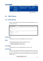
Page 133: ... Mode Configure operation mode to enable disable DHCP server per system Mode Configure the operation mode per system Possible modes are Enabled Enable DHCP server per system Disabled Disable DHCP server per system VLAN Mode Configure operation mode to enable disable DHCP server per VLAN VLAN Range Indicate the VLAN range in which DHCP server is enabled or disabled The first VLAN ID must be smaller...

Page 134: ...sabled Disable DHCP server per VLAN Buttons Add VLAN range click to add new VLAN range Save Click to save changes Undo Click to undo any changes made locally and revert to previously saved values 6 3 2 Reserve IP configuration This page configures excluded IP addresses DHCP server will not allocate these excluded IP addresses to DHCP client Excluded IP Address Configure excluded IP addresses IP Ra...

Page 135: ...pe IP subnet mask and lease time you can click the pool name to go into the configuration page Name Configure the pool name that accepts all printable characters except white space If you want to configure the detail settings you can click the pool name to go into the configuration page Type Display which type of the pool is Network the pool defines a pool of IP addresses to service more than one ...

Page 136: ...ase Time Display lease time of the pool Buttons Add new address pool click to add a DHCP pool Save Click to save changes Undo Click to undo any changes made locally and revert to previously saved values 6 3 3 1 DHCP Pool Configuration This page configures all settings of a DHCP pool ...

Page 137: ...User Manual 3onedata proprietary and confidential Copyright 3onedata Co Ltd 127 ...

Page 138: ...nt identifier or hardware address IP Specify network number of the DHCP address pool Subnet Mask DHCP option 1 Specify subnet mask of the DHCP address pool Lease Time DHCP option 51 58 and 59 Specified Lease Time Allow the client to request a lease time for the IP address If all are 0 s then it means the lease time is infinite Domain Name DHCP option 15 Specify domain name that client should use w...

Page 139: ...ist of NBNS name servers listed in order of preference NIS Domain Name DHCP option 40 Specify the name of NIS domain of the client NIS Server DHCP option41 Specify a list of IP addresses indicating NIS servers available to the client Client Identifier DHCP option61 Specify client s unique identifier to be used when the pool is the type of host Hardware Address Specify client s hardware MAC address...

Page 140: ... TFTP server address specifies the address of the TFTP server assigned to the client Pool File 67 Set boot filename option to specify the boot filename assigned to the client Buttons Save Click to save changes Undo Click to undo any changes made locally and revert to previously saved values 6 3 4 Statistics Monitoring DHCP Server Statistics This page displays the database counters and the number o...

Page 141: ...t type Expired Binding Number of bindings that their lease time expired or they are cleared from Automatic Manual type bindings DHCP Message Received Counters Display counters of DHCP messages received by DHCP server DISCOVER Number of DHCP DISCOVER messages received REQUEST Number of DHCP REQUEST messages received DECLINE Number of DHCP DECLINE messages received RELEASE Number of DHCP RELEASE mes...

Page 142: ...inding Monitoring DHCP Server Binding IP This page displays bindings generated for DHCP clients Binding IP Address Display all bindings IP IP address allocated to DHCP client Type Type of binding Possible types are Automatic Manual Expired Status State of binding Possible states are Committed Allocated Expired Pool Name The pool that generates the binding Server ID Server IP address to service the...

Page 143: ...lict Monitoring DHCP Server Declined IP This page displays declined IP addresses Declined IP Addresses Display IP addresses declined by DHCP clients Declined IP List of IP addresses declined Buttons Auto refresh Check this box to refresh the page automatically Automatic refresh occurs every 3 seconds Refresh Click to refresh the page immediately 6 4 DHCP Relay 6 4 1 Relay Configuration A DHCP rela...

Page 144: ...r Indicates the DHCP relay server IP address Relay Information Mode Indicates the DHCP relay information mode option operation The option 82 circuit ID format as vlan_id module_id port_no The first four characters represent the VLAN ID the fifth and sixth characters are the module ID in standalone device it always equal 0 in stackable device it means switch ID and the last two characters are the p...

Page 145: ...nformation mode is disabled Possible policies are Replace Replace the original relay information when a DHCP message that already contains it is received Keep Keep the original relay information when a DHCP message that already contains it is received Delete Drop the package when a DHCP message that already contains relay information is received Buttons Save Click to save changes Undo Click to und...

Page 146: ... match known Remote ID Client Statistics Transmit to Client The number of relayed packets from server to client Transmit Error The number of packets that resulted in error while being sent to servers Receive from Client The number of received packets from server Receive Agent Option The number of received packets with relay agent information option Replace Agent Option The number of packets which ...

Page 147: ...oping mode operation is enabled the DHCP request messages will be forwarded to trusted ports and only allow reply packets from trusted ports Disabled Disable DHCP snooping mode operation Port Mode Configuration Indicates the DHCP snooping port mode Possible port modes are Trusted Configures the port as trusted source of the DHCP messages Untrusted Configures the port as untrusted source of the DHC...

Page 148: ...eginning of the Dynamic DHCP snooping Table The MAC address and VLAN input fields allows the user to select the starting point in the Dynamic DHCP snooping Table Clicking the Refresh button will update the displayed table starting from that or the closest next Dynamic DHCP snooping Table match In addition the two input fields will upon a Refresh button click assume the value of the first displayed...

Page 149: ...s Updates the table starting from the first entry in the Dynamic DHCP snooping Table Updates the table starting with the entry after the last entry currently displayed 6 6 DHCP Detailed Statistics This page provides statistics for DHCP snooping Notice that the normal forward per port TX statistics isn t increased if the incoming DHCP packet is done by L3 forwarding mechanism And clear the statisti...

Page 150: ...number of inform option 53 with value 8 packets received and transmitted Rx and Tx Lease Query The number of lease query option 53 with value 10 packets received and transmitted Rx and Tx Lease Unassigned The number of lease unassigned option 53 with value 11 packets received and transmitted Rx and Tx Lease Unknown The number of lease unknown option 53 with value 12 packets received and transmitte...

Page 151: ... Clears the counters for all ports 6 7 LLDP 6 7 1 LLDP Configuration This page allows the user to inspect and configure the current LLDP interface settings 6 7 1 1 LLDP Parameters Send interval The switch periodically transmits LLDP frames to its neighbors for having the network discovery information up to date The interval between each LLDP frame is determined by the Tx Interval value Valid value...

Page 152: ...ng units signaling that the LLDP information isn t valid anymore Tx Reinit controls the amount of seconds between the shutdown frame and a new LLDP initialization Valid values are restricted to 1 10 seconds 6 7 1 2 LLDP Interface Configuration Interface The switch interface name of the logical LLDP interface Mode Select LLDP mode Rx only The switch will not send out LLDP information but LLDP infor...

Page 153: ...ties that are not part of the LLDP These capabilities are shown as others in the LLDP neighbors table If all interfaces have CDP awareness disabled the switch forwards CDP frames received from neighbor devices If at least one interface has CDP awareness enabled all CDP frames are terminated by the switch Note When CDP awareness on an interface is disabled the CDP information isn t removed immediat...

Page 154: ...al Interface The interface on which the LLDP frame was received Chassis ID The Chassis ID is the identification of the neighbor s LLDP frames Port ID The Port ID is the identification of the neighbor port Port Description Port Description is the port description advertised by the neighbor unit System Name System Name is the name advertised by the neighbor unit System Capabilities System Capabiliti...

Page 155: ...stance hold the neighbor s IP address Buttons Auto refresh Check this box to refresh the page automatically Automatic refresh occurs every 3 seconds Refresh Click to refresh the page 6 7 3 Port Statistics Monitoring This page provides an overview of all LLDP traffic Two types of counters are shown Global counters are counters that refer to the whole switch while local counters refer to per interfa...

Page 156: ...mation Local Interface The interface on which LLDP frames are received or transmitted Tx Frames The number of LLDP frames transmitted on the interface Rx Frames The number of LLDP frames received on the interface Rx Errors The number of received LLDP frames containing some kind of error Frames Discarded If a LLDP frame is received on a interface and the switch s internal table has run full the LLD...

Page 157: ...s removed and the Age Out counter is incremented Clear If checked the counters for the specific interface are cleared when is pressed Buttons Auto refresh Check this box to refresh the page automatically Automatic refresh occurs every 3 seconds Refresh Click to refresh the page Clear Clear the counters which have the corresponding checkbox checked 6 8 Storm Policing Global Storm Policer Configurat...

Page 158: ...00 when Unit is fps and 1 1024 when Unit is kfps The rate is internally rounded up to the nearest value supported by the global storm policer Unit Controls the unit of measure for the global storm policer rate as fps or kfps Buttons Save Click to save changes Reset Click to undo any changes made locally and revert to previously saved values 6 9 Loop Protection 6 9 1 Loop Protection Configuration T...

Page 159: ...d values are 1 to 10 seconds Default value is 5 seconds Shutdown Time The period in seconds for which a port will be kept disabled in the event of a loop is detected and the port action shuts down the port Valid values are 0 to 604800 seconds 7 days A value of zero will keep a port disabled until next device restart Default value is 180 seconds Port Configuration Port The switch port number Enable...

Page 160: ...hanges Undo Click to undo any changes made locally and revert to previously saved values 6 9 2 Loop Protection Status This page displays the loop protection port status the ports of the switch Loop protection port status is Port The switch port number of the logical port ACTION The currently configured port action Transmit The currently configured port transmit mode Loops The number of loops detec...

Page 161: ...regular intervals 6 10 Static Aggregation 6 10 1 Aggregation Mode Configuration This page is used to configure the Aggregation hash mode and the aggregation group 6 10 1 1 Hash Code Contributors Source MAC Address The Source MAC address can be used to calculate the destination port for the frame Check to enable the use of the Source MAC address or uncheck to disable By default Source MAC Address i...

Page 162: ...the TCP UDP Port Number or uncheck to disable By default TCP UDP Port Number is enabled 6 10 1 2 Aggregation Group Configuration Group ID Indicates the group ID for the settings contained in the same row Group ID Normal indicates there is no aggregation Only one group ID is valid per port Configured ports Each switch port is listed for each group ID Select a radio button to include a port in an ag...

Page 163: ... group Static or LACP Speed Speed of the Aggregation group Configured ports Configured member ports of the Aggregation group Aggregated ports Aggregated member ports of the Aggregation group Buttons Refresh Click to refresh the page immediately Auto refresh Automatic refresh occurs every 3 seconds 6 11 LACP 6 11 1 LACP Configuration This page allows the user to inspect the current LACP port config...

Page 164: ...e LACP activity status The Active will transmit LACP packets each second while Passive will wait for a LACP packet from a partner speak if spoken to Timeout The Timeout controls the period between BPDU transmissions Fast will transmit LACP packets each second while Slow will wait for 30 seconds before sending a LACP packet Prio The priority of the control port range 1 65535 If the LACP partner wan...

Page 165: ...ch ports are a part of this aggregation for this switch Buttons Refresh Click to refresh the page immediately Auto refresh Automatic refresh occurs every 3 seconds 6 11 3 Port State Monitoring This page provides a status overview for LACP status for all ports Port The switch port number LACP Yes means that LACP is enabled and the port link is up No means that LACP is not enabled or that the port l...

Page 166: ...Auto refresh Automatic refresh occurs every 3 seconds 6 11 4 Port Monitoring Statistics This page provides an overview for LACP statistics for all ports Port The switch port number LACP Received Shows how many LACP frames have been received at each port LACP Transmitted Shows how many LACP frames have been sent from each port Discarded Shows how many unknown or illegal LACP frames have been discar...

Page 167: ...nd MSTP Bridge Priority Controls the bridge priority Lower numeric values have better priority The bridge priority plus the MSTI instance number concatenated with the 6 byte MAC address of the switch forms a Bridge Identifier For MSTP operation this is the priority of the CIST Otherwise this is the priority of the STP RSTP bridge Hello Time The interval between sending STP BPDU s Valid values are ...

Page 168: ...nsmission of the next BPDU will be delayed Valid values are in the range 1 to 10 BPDU s per second 6 12 1 2 Advanced Settings Edge Port BPDU Filtering Control whether a port explicitly configured as Edge will transmit and receive BPDUs BPDU Guard Control whether a port explicitly configured as Edge will disable itself upon reception of a BPDU The port will enter the error disabled state and will b...

Page 169: ...mapping configuration in order to share spanning trees for MSTI s Intra region The name is at most 32 characters Configuration Revision The revision of the MSTI configuration named above This must be an integer between 0 and 65535 6 12 2 2 MSTI Mapping MSTI The Bridge Instance The CIST is not available for explicit mapping as it will receive the VLANs not explicitly mapped VLANs Mapped The list of...

Page 170: ...configurations and possibly change them as well MSTI The Bridge Instance The CIST is the default instance which is always active Priority Controls the bridge priority Lower numeric values have better priority The bridge priority plus the MSTI instance number concatenated with the 6 byte MAC address of the switch forms a Bridge Identifier Buttons Save Click to save changes Undo Click to undo any ch...

Page 171: ... path cost ports are chosen as forwarding ports in favour of higher path cost ports Valid values are in the range 1 to 200000000 Priority Controls the port priority This can be used to control priority of ports having identical port cost See above operEdge state flag Operational flag describing whether the port is connecting directly to edge devices No Bridges attached Transition to the forwarding...

Page 172: ...o other ports If set it can cause temporary loss of connectivity after changes in a spanning tree s active topology as a result of persistently incorrect learned station location information It is set by a network administrator to prevent bridges external to a core region of the network causing address flushing in that region possibly because those bridges are not under the full control of the adm...

Page 173: ...to setting will set the path cost as appropriate by the physical link speed using the 802 1D recommended values Using the Specific setting a user defined value can be entered The path cost is used when establishing the active topology of the network Lower path cost ports are chosen as forwarding ports in favour of higher path cost ports Valid values are in the range 1 to 200000000 Priority Control...

Page 174: ...ost Root Path Cost For the Root Bridge this is zero For all other Bridges it is the sum of the Port Path Costs on the least cost path to the Root Bridge Topology Flag The current state of the Topology Change Flag of this Bridge instance Topology Change Last The time since last Topology Change occurred Buttons Refresh Click to refresh the page immediately Auto refresh Check this box to refresh the ...

Page 175: ...al Root Cost The Regional Root Path Cost For the Regional Root Bridge this is zero For all other CIST instances in the same MSTP region it is the sum of the Internal Port Path Costs on the least cost path to the Internal Root Bridge For the CIST instance only Topology Flag The current state of the Topology Change Flag of this Bridge instance Topology Change Count The number of times where the topo...

Page 176: ...ag may be automatically computed or explicitly configured Each Edge Port transits directly to the Forwarding Port State since there is no possibility of it participating in a loop Point to Point The current STP port point to point flag A point to point port connects to a non shared LAN media The flag may be automatically computed or explicitly configured The point to point properties of a port aff...

Page 177: ...tialized Buttons Refresh Click to refresh the page immediately Auto refresh Check this box to refresh the page automatically Automatic refresh occurs every 3 seconds 6 12 8 Port Statistics Monitoring This page displays the STP port statistics counters of bridge ports in the switch The STP port statistics counters are Port The switch port number MSTP The number of MSTP BPDU s received transmitted o...

Page 178: ...ear Click to reset the counters Auto refresh Check this box to enable an automatic refresh Automatic refresh occurs every 3 seconds 6 13 Ring 6 13 1 Ring Configuration This page provides ring related configurations It provides automatic recovery and reconnection mechanism for the disconnected Ethernet network which has link redundancy and self recovery ability in case of network interruption or ne...

Page 179: ... type of redundant network topology structure via a kind of advanced software technology Dual homing Two adjacent rings share a switch users can carry the same switch on two different networks or two different switching devices on the same network Port1 The network port 1 on the switch device used to form the ring network Port2 The network port 2 on the switch device used to form the ring network ...

Page 180: ... device option One Master Multi Slave mode is recommended in one single ring When the device is set as master device and one end of it is backup link it can enable backup link to ensure the normal operation of the network when failure occurs in ring network Note Some products don t support Master slave option so their ring network is non master station structure Port1 The network port 1 on the swi...

Page 181: ... a MEP in the EVC Domain Flow Instance is an EVC The EVC must be created VLAN This is a MEP in the VLAN Domain Flow Instance is a VLAN In case of Up MEP the VLAN must be created Mode MEP This is a Maintenance Entity End Point MIP This is a Maintenance Entity Intermediate Point Direction Down This is a Down MEP monitoring ingress OAM and traffic on Residence Port Up This is a Up MEP monitoring egre...

Page 182: ...d EVC MIP On Serval this is the Subscriber VID that identifies the subscriber flow in this EVC where the MIP is active This MAC The MAC of this MEP can be used by other MEP when unicast is selected Info only Alarm There is an active alarm on the MEP Buttons Add new MEP Click to add a new MEP entry Refresh Click to refresh the page immediately Save Click to save changes Undo Click to undo any chang...

Page 183: ... Domain Port This is a MEP in the Port Domain EVC This is a MEP in the EVC Domain Flow Instance is an EVC The EVC must be created VLAN This is a MEP in the VLAN Domain Flow Instance is a VLAN In case of Up MEP the VLAN must be created Mode MEP This is a Maintenance Entity End Point MIP This is a Maintenance Entity Intermediate Point ...

Page 184: ...his VID Entering 0 means no TAG added EVC MEP This is not used VLAN MEP This is not used EVC MIP On Serval this is the Subscriber VID that identifies the subscriber flow in this EVC where the MIP is active This MAC The MAC of this MEP can be used by other MEP when unicast is selected Info only 6 14 2 2 Instance Configuration EVC QoS This is only relevant for a EVC MEP This is the Qos of the EVC an...

Page 185: ...E String format this can be max 16 char MEP Id This value will become the transmitted two byte CCM MEP ID Tagged VID This value will be the VID of a TAG added to the OAM PDU VOE This will attempt to utilize VOE HW for MEP implementation Not all platforms support VOE cLevel Fault Cause indicating that a CCM is received with a lower level than the configured for this MEP cMEG Fault Cause indicating ...

Page 186: ...pected MEP ID in a received CCM see cMEP Unicast Peer MAC This MAC will be used when unicast is selected with this peer MEP Also this MAC is used to create HW checking of receiving CCM PDU LOC detection from this MEP cLOC Fault Cause indicating that no CCM has been received in 3 5 periods from this peer MEP cRDI Fault Cause indicating that a CCM is received with Remote Defect Indication from this ...

Page 187: ... of the CCM PDU Fault Cause cLOC is declared if no CCM PDU has been received within 3 5 periods see cLOC Fault Cause cPeriod is declared if a CCM PDU has been received with different period see cPeriod Selecting 300f sec or 100f sec will configure HW based CCM if possible Selecting other frame rates will configure SW based CCM In case of enable of Continuity Check and Loss Measurement both impleme...

Page 188: ...octet is 01 and the usage of other values is for further study 6 14 2 5 TLV Configuration Configuration of the OAM PDU TLV Currently only TLV in the CCM is supported Organization Specific OUI First The transmitted first value in the OS TLV OUI field Organization Specific OUI Second The transmitted second value in the OS TLV OUI field Organization Specific OUI Third The transmitted third value in t...

Page 189: ...rface Status Value The last received value in the IS TLV Value field CC Interface Status Last RX IS TLV was received in the last received CCM PDU 6 14 2 7 Link State Tracking Enable When LST is enabled in an instance Local SF or received isDown in CCM Interface Status TLV will bring down the residence port Only valid in Up MEP The CCM rate must be 1 f s or faster Buttons Fault management Click to ...

Page 190: ...k based on transmitting receiving LBM LBR PDU can be enabled disabled Loop Back is automatically disabled when all To Send LBM PDU has been transmitted waiting 5 sec for all LBR from the end DEI The DEI to be inserted as PCP bits in TAG if any Priority The priority to be inserted as PCP bits in TAG if any ...

Page 191: ... size This is entered as the wanted size in bytes of a un tagged frame containing LBM OAM PDU including CRC four bytes Example when Size 64 Un tagged frame size DMAC 6 SMAC 6 TYPE 2 TST PDU LENGTH 46 CRC 4 64 bytes The transmitted frame will be four bytes longer for each tag added 8 bytes in case of a tunnel EVC There are two frame MAX sizes to consider Switch RX frame MAX size The MAX frame size ...

Page 192: ... Link Trace based on transmitting receiving LTM LTR PDU can be enabled disabled Link Trace is automatically disabled when all 5 transactions are done with 5 sec interval waiting 5 sec for all LTR in the end The LTM PDU is always transmitted as Multi cast Class 2 Priority The priority to be inserted as PCP bits in TAG if any Peer MEP This is only used if the Unicast MAC is configured to all zero Th...

Page 193: ... MIP sending this LTR Direction Indicating if MEP MIP sending this LTR is ingress egress Forwarded Indicating if MEP MIP sending this LTR has forwarded the LTM Relay The Relay action can be one of the following MAC The was a hit on the LT Target MAC FDB LTM is forwarded based on data in the Filtering DB MFDB LTM is forwarded based on data in the MIP CCM DB Last MAC The MAC identifying the last sen...

Page 194: ...nger for each tag added 8 bytes in case of a tunnel EVC There are two frame MAX sizes to consider Switch RX frame MAX size The MAX frame size all inclusive accepted on the switch port of 9600 Bytes CPU RX frame MAX size The MAX frame size all inclusive possible to copy to CPU of 1526 Bytes Consider that the Peer MEP must be able to handle the selected frame size Consider that in order to calculate...

Page 195: ...al State Transmission of TST frame will be restarted Calculation of Rx frame count RX rate and Test time will be started when receiving first TST frame Client Configuration Only a Port MEP is able to be a server MEP with flow configuration The Priority in the client flow is always the highest priority configured in the EVC Domain The domain of the client layer flow Inst Client layer flow instance ...

Page 196: ... this for protection in the end point LOCK Enable Insertion of LOCK signal LCK PDU transmission in client layer flows can be enable disabled Frame Rate Selecting the frame rate of LCK PDU This is the inverse of transmission period as described in Y 1731 Buttons Refresh Click to refresh the page immediately Back Click to go back to this MEP instance main page Save Click to save changes Undo Click t...

Page 197: ...oss Measurement Tx Loss Measurement initiator is enabled disabled Initiator is transmitting receiving CCM or LMM LMR or SLM SLR 1SL PDUs see Synthetic and Ended Service frame LM not Synthetic is only allowed with one Peer MEP configured Synthetic frame LM is allowed with multiple Peer MEPs configured Received Enable loss calculation when receiving LM PDUs LMM SLM 1SL This is ignored when LM initia...

Page 198: ...f Synthetic LM Selecting 6f min is not valid in case of dual ended Service frame LM CCM PDU based In case of enable of Continuity Check and Loss Measurement both implemented on SW based CCM Frame Rate has to be the same Size The Synthetic SLM 1SL frame size This is entered as the wanted size in bytes of a un tagged frame containing LM OAM PDU including CRC four bytes Example when Size 64 Un tagged...

Page 199: ...loss and FLR is calculated based on the counted number of SL OAM PDUs It is in this interval that the calculated FLR is checked against availability high loss and degraded FLR threshold For example Rate 100f sec Meas Interval N 10 milliseconds For example Rate 10f sec Meas Interval N 100 milliseconds In case of service frame based LM this attribute is not used and the measurement interval is alway...

Page 200: ...ansmitted in the latest FLR Interval This is shown in Loss Tx 10000 Same as 1 100 Percent Total Near End Loss Ratio The near end frame loss ratio calculated based on the near end frame loss count and far end frame transmitted since last clear This is shown in Loss Tx 10000 Same as 1 100 Percent Total Far End Loss Ratio The far end frame loss ratio calculated based on the far end frame loss count a...

Page 201: ...ment High Loss Interval Enable Enable disable of loss measurement high loss interval FLR Threshold High Loss Interval frame loss ratio threshold in per mille Consecutive Interval High Loss Interval consecutive interval number of measurements Loss Measurement High Loss Interval Status Near Count Near end high loss interval count number of measurements where availability state is available and FLR i...

Page 202: ... consecutive good interval measurements required to clear degrade state Delay Measurement Enable Delay Measurement based on transmitting 1DM DMM PDU can be enabled disabled Delay Measurement based on receiving and handling 1DM DMR PDU is always enabled Priority The priority to be inserted as PCP bits in TAG if any Cast Selection of 1DM DMM PDU transmitted unicast or multicast The unicast MAC will ...

Page 203: ... is 10 to 2000 Unit The time resolution Synchronized Enable to use DMM DMR packet to calculate dual ended DM If the option is enabled the following action will be taken When DMR is received two way delay roundtrip or flow and both near end to far end and far end to near end one way delay are calculated When DMM or 1DM is received only far end to near end one way delay is calculated Counter Overflo...

Page 204: ...of counter overflow since last clear Clear Set of this check and save will clear the accumulated counters Far end to near end one way delay The one way delay is from remote devices to the local devices Here are the conditions to calculate this delay DM received by 1 2DMM received with Synchronized enabled 3DMR received with Synchronized enabled Near end to far end one way delay The one way delay i...

Page 205: ...r each Measurement Bin The unit for a measurement threshold is in microseconds us The default configured measurement threshold for a Measurement Bin is an increment of 5000 us Delay Measurement Bins for FD A Measurement Bin is a counter that stores the number of delay measurements falling within a specified range during a Measurement Interval If the measurement threshold is 5000 us and the total n...

Page 206: ... 1 ERPS The ERPS instances are configured here Delete This box is used to mark an ERPS for deletion in next save operation ERPS ID The ID of the created Protection group It must be an integer value between 1 and 64 The maximum numbers of ERPS Protection Groups that can be created are 64 Click on the ID of a Protection group to enter the configuration page Port 0 This will create a Port 0 of the sw...

Page 207: ...nterconnected Node indicates that the ring instance is interconnected Click on the checkbox to configure this Yes indicates it is an interconnected node for this instance No indicates that the configured instance is not interconnected Virtual Channel Sub rings can either have virtual channel or not on the interconnected node This is configured using Virtual Channel checkbox Yes indicates it is a s...

Page 208: ...ck on the ID of a Protection group to enter the configuration page Port 0 This will create a Port 0 of the switch in the ring Port 1 This will create Port 1 of the switch in the Ring As interconnected sub ring will have only one ring port Port 1 is configured as 0 for interconnected sub ring 0 in this field indicates that no Port 1 is associated with this instance Port 0 SF MEP The Port 0 Signal F...

Page 209: ...ted with this instance Ring Type Type of Protecting ring It can be either major ring or sub ring Interconnected Node Interconnected Node indicates that the ring instance is interconnected Click on the checkbox to configure this Yes indicates it is an interconnected node for this instance No indicates that the configured instance is not interconnected Buttons Add new protection group Click to add a...

Page 210: ... ring without virtual channel it is configured as 0 for such ring instances 0 in this field indicates that no Port 1 APS MEP is associated with this instance Port 0 APS MEP The Port 0 APS PDU handling MEP Port 1 APS MEP The Port 1 APS PDU handling MEP As only one APS MEP is associated with interconnected sub ring without virtual channel it is configured as 0 for such ring instances 0 in this field...

Page 211: ...evertive mode after the conditions causing a protection switch has cleared the traffic channel is restored to the working transport entity i e blocked on the RPL In Non Revertive mode the traffic channel continues to use the RPL if it is not failed after a protection switch condition has cleared VLAN config VLAN configuration of the Protection Group Click on the VLAN Config link to configure VLANs...

Page 212: ...local administrative command e g Forced Switch or Manual Switch Port Port selection Port0 or Port1 of the protection Group on which the command is applied Instance State Protection State ERPS state according to State Transition Tables in G 8032 Port 0 OK State of East port is ok SF State of East port is Signal Fail Port 1 OK State of West port is ok SF State of West port is Signal Fail Transmit AP...

Page 213: ... and R APS block status R APS channel is never blocked on sub rings without virtual channel FOP Alarm Failure of Protocol Defect FOP status If FOP is detected red LED glows else green LED glows Buttons Save Click to save changes Auto refresh Check this box to enable an automatic refresh Automatic refresh occurs every 3 seconds Refresh Click to refresh the page immediately Undo Click to undo any ch...

Page 214: ...ugh 4095 The VLAN is enabled when you click on Save A VLAN without any port members will be deleted when you click Save The Delete button can be used to undo the addition of new VLANs Buttons Save Click to save changes Undo Click to undo any changes made locally and revert to previously saved values Refresh Refreshes the displayed table starting from the VLAN ID input fields ...

Page 215: ...bled Enable unregistered IPMCv4 traffic flooding The flooding control takes effect only when IGMP Snooping is enabled When IGMP Snooping is disabled unregistered IPMCv4 traffic flooding is always active in spite of this setting IGMP SSM Range SSM Source Specific Multicast Range allows the SSM aware hosts and routers run the SSM service model for the groups in the address range Assign valid IPv4 mu...

Page 216: ... undo any changes made locally and revert to previously saved values 7 1 2 VLAN Configuration Navigating the IGMP Snooping VLAN Table Each page shows up to 99 entries from the VLAN table default being 20 selected through the entries per page input field When first visited the web page will show the first 20 entries from the beginning of the VLAN Table The first displayed will be the one with the l...

Page 217: ...uerier election When the Querier address is not set system uses IPv4 management address of the IP interface associated with this VLAN When the IPv4 management address is not set system uses the first available IPv4 management address Otherwise system uses a pre defined value By default this value will be 192 0 2 1 IGMP Versions Compatibility is maintained by hosts and routers taking appropriate ac...

Page 218: ...tarts working after the corresponding static VLAN is also created Save Click to save changes Undo Click to undo any changes made locally and revert to previously saved values 7 1 3 Status Monitoring This page provides IGMP Snooping status VLAN ID The VLAN ID of the entry Querier Version Working Querier Version currently Host Version Working Host Version currently Querier Status Shows the Querier s...

Page 219: ...ulticast device or IGMP querier Static denotes the specific port is configured to be a router port Dynamic denotes the specific port is learnt to be a router port Both denote the specific port is configured or learnt to be a router port Port The switch port number Status Indicate whether specific port is a router port or not Buttons Auto refresh Automatic refresh occurs every 3 seconds Refresh Cli...

Page 220: ...closest next IGMP Group Table match In addition the two input fields will upon a Refresh button click assume the value of the first displayed entry allowing for continuous refresh with the same start address The will use the last entry of the currently displayed table as a basis for the next lookup When the end is reached the text No more entries is shown in the displayed table Use the button to s...

Page 221: ...e entries per page input field When first visited the web page will show the first 20 entries from the beginning of the IGMP SFM Information Table The Start from VLAN and Group input fields allow the user to select the starting point in the IGMP SFM Information Table Clicking the Refresh button will update the displayed table starting from that or the closest next IGMP SFM Information Table match ...

Page 222: ...e is shown in the Source Address field Type Indicates the Type It can be either Allow or Deny Hardware Filter Switch Indicates whether data plane destined to the specific group address from the source IPv4 address could be handled by chip or not Buttons Auto refresh Automatic refresh occurs every 3 seconds Refresh Refresh the displayed table starting from the input fields Updates the table startin...

Page 223: ...The VLAN ID of the entry MAC address The multicast MAC address of the entry such as 01 00 5E XX XX XX Configured ports The ports that are members of the entry Buttons Add new static entry click to add a new static multicast MAC address entry Save Click to save changes Undo Click to undo any changes made locally and revert to previously saved values ...

Page 224: ...is page allows the user to inspect and configure the current PoE port settings Reserved Power determined by There are three modes for configuring how the ports PDs may reserve power Allocated mode In this mode the user allocates the amount of power that each port may reserve The allocated reserved power for each port PD is specified in ...

Page 225: ...en to shut down the ports Actual consumption In this mode the ports are shut down when the actual power consumption for all ports exceeds the amount of power that the power supply can deliver or if the actual power consumption for a given port exceeds the reserved power for that port The ports are shut down according to the ports priority If two ports have the same priority the port with the highe...

Page 226: ...quires more power than the power supply can deliver In this case the port with the lowest priority will be turn off starting from the port with the highest port number Maximum Power The Maximum Power value contains a numerical value that indicates the maximum power in watts that can be delivered to a remote device The maximum allowed value is 30 W Buttons Save Click to save changes Reset Click to ...

Page 227: ...priority configured by the user Port Status The Port Status shows the port s status The status can be one of the following values PoE not available No PoE chip found PoE not supported for the port PoE turned OFF PoE disabled PoE is disabled by user PoE turned OFF Power budget exceeded The total requested or used power by the PDs exceeds the maximum power the Power Supply can deliver and port s wit...

Page 228: ...stant power supply shock when the device is powered on After the device is powered on the PoE port first waits for Delay Time and then powers the PD Delay Mode Enable Delay Mode or not options as follows Enable Disable Delay Time Delay power supply of PoE port Buttons Save Click to save changes Reset Click to undo any changes made locally and revert to previously saved values ...

Page 229: ...eriods and then reference the time periods in the rule the rule will be valid only for the specified time period Users that adopt the same name can configure multiple time segments with different contents After gain the union of each cycle time period and each absolute time period the intersection of each union will become the final valid time range Delete Delete one scheduling user record Name Us...

Page 230: ...duling or Abosolute scheduling PStartTime Starting time of relative time format HH MM Hour Minute PEndtime End time of relative time format HH MM Hour Minute PWeek Cycle date of relative time take one week as a cycle A StartTime Starting time of absolute time format HH MM Hour Minute A StartYear End date of absolute time format YYYY MM DD Year month day A EndTime End time of absolute time format H...

Page 231: ...alues Status User s current status it could be Inactive or active Type The type of scheduling policy Periodic scheduling or Abosolute scheduling Time range Plan time Buttons Add New Name Click to add new name Save Click to save changes Reset Click to undo any changes made locally and revert to previously saved values 8 3 2 Policy Binding This page can configure the port to bind PoE scheduling sche...

Page 232: ...bind it to the port 8 4 Auto check This page can automatically monitor the PoE status of the port Ping IP Address Ping the IP address of the remote device Startup Time Startup time reserved not enabled Interval Elapsed Test period Retry Time Retry times Failure log Failure log Failure Action Troubleshooting Reboot Time Reboot delay ...

Page 233: ...ontrols the default class of service All frames are classified to a CoS There is a one to one mapping between CoS queue and priority A CoS of 0 zero has the lowest priority If the port is VLAN aware the frame is tagged and Tag Class is enabled then the frame is classified to a CoS that is mapped from the PCP and DEI value in the tag Otherwise the frame is classified to the default CoS The classifi...

Page 234: ...e classified to a DEI value If the port is VLAN aware and the frame is tagged then the frame is classified to the DEI value in the tag Otherwise the frame is classified to the default DEI value Tag Class Display the classification mode of label frames on this port Display the label classification of tagged frames on this port Disabled Use default CoS and DPL for tagged frames Enabled Use mapped ve...

Page 235: ...for which the configuration below applies Enable Enable or disable the port policer for this switch port Rate Controls the rate for the port policer This value is restricted to 100 3276700 when Unit is kbps or fps and 1 3276 when Unit is Mbps or kfps The rate is internally rounded up to the nearest value supported by the port policer Unit Controls the unit of measure for the port policer rate as k...

Page 236: ...ber for which the configuration below applies Enable E Enable or disable the queue policer for this switch port Rate Controls the rate for the queue policer This value is restricted to 100 3276700 when Unit is kbps and 1 3276 when Unit is Mbps The rate is internally rounded up to the nearest value supported by the queue policer This field is only shown if at least one of the queue policers are ena...

Page 237: ...ers This page provides an overview of QoS Egress Port Schedulers for all switch ports The displayed settings are Port The switch port number Click on the port number in order to configure the schedulers Mode Shows the scheduling mode for this port Qn Shows the weight for this queue and port 9 5 QoS Egress Port Shapers This page provides an overview of QoS Egress Port Shapers for all switch ports T...

Page 238: ... Port Remarking This page provides an overview of QoS Egress Port Tag Remarking for all switch ports The displayed settings are Port The switch port number Click on the port number in order to configure tag remarking Mode Shows the tag remarking mode for this port Classified Use classified PCP DEI values Default Use default PCP DEI values Mapped Use mapped versions of QoS class and DP level 9 7 Po...

Page 239: ...available in Ingress 1Transformation 2Class 1Transformation To Enable the Ingress Translation click the checkbox 2Class Classification for a port have 4 different values Disable No Ingress DSCP Classification DSCP 0 Classify if incoming or translated if enabled DSCP is 0 Selected Classify only selected DSCP for which classification is enabled as specified in DSCP Translation window for the specifi...

Page 240: ...e is remarked with remapped DSCP value Depending on the DP level of the frame the remapped DSCP value is either taken from the DSCP Translation Egress Remap DP0 table or from the DSCP Translation Egress Remap DP1 table Buttons Save Click to save changes Undo Click to undo any changes made locally and revert to previously saved values 9 8 DSCP based QoS Ingress Classification This page allows you t...

Page 241: ...User Manual 3onedata proprietary and confidential Copyright 3onedata Co Ltd 231 ...

Page 242: ... Precedence Level Frames with untrusted DSCP values are treated as a non IP frame QoS Classification QoS class value can be any of 0 7 DPL Drop Precedence Level 0 1 Buttons Save Click to save changes Undo Click to undo any changes made locally and revert to previously saved values 9 9 DSCP Translation This page allows you to configure the basic QoS DSCP Translation settings for all switches DSCP t...

Page 243: ...User Manual 3onedata proprietary and confidential Copyright 3onedata Co Ltd 233 ...

Page 244: ...on at Ingress side Egress There are the following configurable parameters for Egress side 1Remap DP0 controls remapping of frames with DP level 0 2Remap DP1 controls the remapping of frames through DP level 1 1Remap DP0 Select the DSCP value from select menu to which you want to remap DSCP value ranges from 0 to 63 2Remap DP1 Select the DSCP value from select menu to which you want to remap DSCP v...

Page 245: ...0 63 for Drop Precedence Level 1 Buttons Save Click to save changes Undo Click to undo any changes made locally and revert to previously saved values 9 11 QoS Control List Configuration QoS Control List Configuration This page shows the QoS Control List QCL which is made up of the QCEs Each row describes a QCE that is defined The maximum number of QCEs is 256 on each switch Click on the lowest plu...

Page 246: ...dresses this field indicates the DMAC Tag Type Indicates tag type Possible values are Any Match tagged and untagged frames Untagged Match untagged frames Tagged Match tagged frames The default value is Any VID Indicates VLAN ID either a specific VID or range of VIDs VID can be in the range 1 4095 or Any PCP Priority Code Point Valid values of PCP are specific 0 1 2 3 4 5 6 7 or range 0 1 2 3 4 5 6...

Page 247: ...op Precedence Level DSCP Classify DSCP value PCP Classify PCP value DEI Classify DEI value Policy Classify ACL Policy number Modification Buttons You can modify each QCE QoS Control Entry in the table using the following buttons Insert a new QCE before the current row Edit QCE move QCE entry up move QCE entry down delete QCE add new QCE entries at the bottom of the QCE list 9 12 QoS Statistics Thi...

Page 248: ... this box to refresh the page automatically Automatic refresh occurs every 3 seconds Refresh Click to refresh the page immediately Clear Clears the counters for all ports 9 13 QCL Status QCL Status This page shows the QCL status by different QCL users Each row describes the QCE that is defined It is a conflict if a specific QCE is not applied to the hardware due to hardware limitations The maximum...

Page 249: ... DSCP value PCP Classify PCP value DEI Classify DEI value Policy Classify ACL Policy number Conflicts Displays Conflict status of QCL entries As H W resources are shared by multiple applications It may happen that resources required to add a QCE may not be available in that case it shows conflict status as Yes otherwise it is always No Please note that conflict can be resolved by releasing the H W...

Page 250: ...d to analyze the network traffic Remote Mirroring is an extend function of Mirroring It can extend the destination port in other switch So the administrator can analyze the network traffic on the other switches If you want to get the tagged mirrored traffic you have to set VLAN egress tagging as Tag All on the reflector port On the other hand if you want to get untagged mirrored traffic you have t...

Page 251: ...figuration Guideline for All Features When the switch is running on Remote Mirroring mode the administrator also needs to check whether or not other features are enabled or disabled For example the administrator is not disabled the MSTP on reflector port All monitor traffic will be blocked on reflector port All recommended settings are described as follows Buttons Save Click to save changes Undo C...

Page 252: ...e page refreshes automatically until responses to all packets are received or until a timeout occurs PING server 10 10 132 20 56 byte data 64 bytes from 10 10 132 20 icmp_seq 0 time 0ms 64 bytes from 10 10 132 20 icmp_seq 1 time 0ms 64 bytes from 10 10 132 20 icmp_seq 2 time 0ms 64 bytes from 10 10 132 20 icmp_seq 3 time 0ms 64 bytes from 10 10 132 20 icmp_seq 4 time 0ms Send 5 data packets receiv...

Page 253: ... length of 7 140m 10 and 100 Mbps ports will be linked down while running VeriPHY Therefore running VeriPHY on a 10 or 100 Mbps management port will cause the switch to stop responding until VeriPHY is complete Port The port where you are requesting VeriPHY Cable Diagnostics Cable Status Port Switch port number pair The status of the cable pair OK Correctly terminated pair Open Open pair Short Sho...

Page 254: ...onfidential Copyright 3onedata Co Ltd 244 Cross B Abnormal cross pair coupling with pair B Cross C Abnormal cross pair coupling with pair C Cross D Abnormal cross pair coupling with pair D Length Length of cable pair m The resolution is 3m ...

Page 255: ...s page Only the IP configuration is retained The new configuration is available immediately which means that no restart is necessary Yes Click to reset the configuration to factory default settings No Click to return to the port status page without reconfiguration Note Restoring factory defaults can also be done by making a physical loopback between port 1 and port 2 within the first minute of the...

Page 256: ...dated and the switch restarts Warning While the firmware is being updated Web access appears to be defunct The front LED flashes Green Off with a frequency of 10 Hz while the firmware update is in progress Do not restart or power off the device at this time or the switch may fail to function afterwards 11 4 Firmware Selection This page provides information about the active and alternate backup fir...

Page 257: ...e to the device will automatically use the primary image slot and activate this The firmware version and date information may be empty for older firmware releases This does not constitute an error Image Information Image The file name of the firmware image from when the image was last updated Version The version of the firmware image Date The date where the firmware was produced Buttons Add altern...

Page 258: ...xist at boot time the switch will start up in default configuration default config A read only file with vendor specific configuration This file is read when the system is restored to default settings Up to 31 other files typically used for configuration backups or alternative configurations 12 1 Save startup config This will copy running config to startup config thus ensuring that the currently a...

Page 259: ...itch except default config which is read only Select the file to upload select the target file on the target file and then click Upload Configuration If the target is running config the file will be applied to the switch configuration This can be achieved in two ways Replace mode the current configuration is completely replaced with the configuration in the uploaded file ...

Page 260: ...e must be deleted 12 4 Activate You can activate any configuration file on the switch except that running config represents the currently active configuration Select the file to activate and click Activate Configuration This will initiate the process of completely replacing the existing configuration with that of the selected file 12 5 Delete It is possible to delete any of the writable files stor...

Page 261: ...ged switch products consumers can get help and solutions in the following ways Internet Service Service Hotline Product repair or replacement 13 1 Internet Service More useful information and tips are available via our company website Website http www 3onedata com 13 2 Service Hotline Users of our company s products could call technical support office for help Our company has professional technica...

Page 262: ...User Manual 3onedata proprietary and confidential Copyright 3onedata Co Ltd 2 company s technical staff and salesmen to complete the product maintenance replacement or return ...

Page 263: ...r Address 3 B Zone 1 Baiwangxin High Technology Industrial Park Song Bai Road Nanshan District Shenzhen 518108 China Technology Support tech support 3onedata com Service Hotline 4008804496 Official Website http www 3onedata com ...

Reviews: