Quick Installation Guide of NPM301 Serial Server Module
3onedata proprietary and confidential
Copyright © 3onedata Co., Ltd.
6
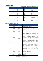
Pin NO
Name
Pin NO
Name
11
TX+
12
TX-
13
ACT
14
LINK
15
nRESET
16
NC
17
NC
18
NC
19
NC
20
NC
21
DEF
22
NC
23
NC
24
COM_CFG
25
NC
26
NC
27
NC
28
GND
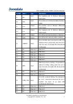
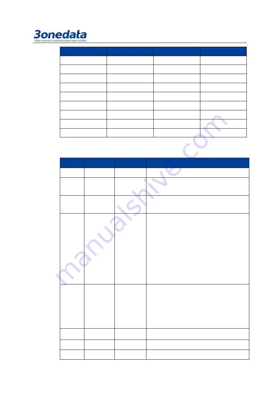
Detailed description of NPM301 pin:
Pin NO
Name
Type
Description
1
VCC
Input
Power input pin: 3.3V±5%
2
DTR
Output
The ready signal pin for digital terminal
device
3
DSR
Input
The
ready
signal
pin
for
digital
communication device
4
RTS/
485EN
Output
Device request signal pins(RS-232 full
duplex mode), LOW permit sending, when
485EN is valid, setting operation in half
duplex mode, data direction control signal
(RS-485 half duplex mode), its direction is
controlled by module automatically. It is
LOW and in receiving state when no data to
send
5
CTS
Input
Pin of device erasing sending signal, when
CTS is valid, setting operation in full duplex
mode, device will erase sending signal
(RS-232 full duplex mode), LOW permit
sending.
6
RXD
Input
(0-5V)TTL level input pin
7
TXD
Output
(0 -3.3V) TTL level output pin
8
NC
Reserved
Reserved

