PS5010G-2GS-8PoE User Manual
6
LED
COLOR
STATUS
STATUS DESCRIPTION
PWR
Green
On
Power On
Off
Power Off
LINK/ACT/
(1-8)
10/100M:
Orange
On
A device is connected to the port
Off
A device is disconnected to the port
1000M:
Green
Flashing
Sending or receiving data
PoE
Yellow
On
A Powered Device is connected to the port,
which supply power successfully
Off
No PD is connected to the corresponding
port, or no power is supplied according to
the power limits of the port
Flashing
The PoE power circuit may be in short or
the power current may be overloaded
LINK/ACT/
(9S-10S)
Green
On
A device is connected to the port
Off
A device is disconnected to the port
Flashing
Sending or receiving data
1.3.2 Rear Panel
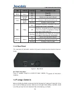
The rear panel of the Switch contains AC power connector and one marker shown as
below.
Figure 3 - Rear Panel
AC Power Connector:
Power is supplied through an external AC power adapter. It supports AC 100~240V,
50/60Hz.
1.4 Package Contents
Before installing the Switch, make sure that the following the "packing list" listed OK. If any
part is lost and damaged, please contact your local agent immediately. In addition, make
sure that you have the tools install switches and cables by your hands.


