background image


TNS5800D Series 

Managed Wall-mounted Industrial 

Ethernet Switch Quick Installation 

Guide 


3onedata Co., Ltd. 


Package Checklist


Please check whether the package and accessories are intact 

while using the switch for the first time.   

1. 

Industrial Ethernet switch 

2.  CD 

3. 

Quick installation guide 

4.  Certification 

5. 

Warranty card 


If any of these items are damaged or lost, please contact our 

company or dealers, we will solve it ASAP.   

Product Overview


The  series  of  product  is  100M/Gigabit  layer  3  managed 

Wall-mounted  industrial  Ethernet  switch  designed  for  rail 

transit industry. The module is: TNS5800D-4GT-8T (4 Gigabit 

copper ports + 8 100M copper ports) 

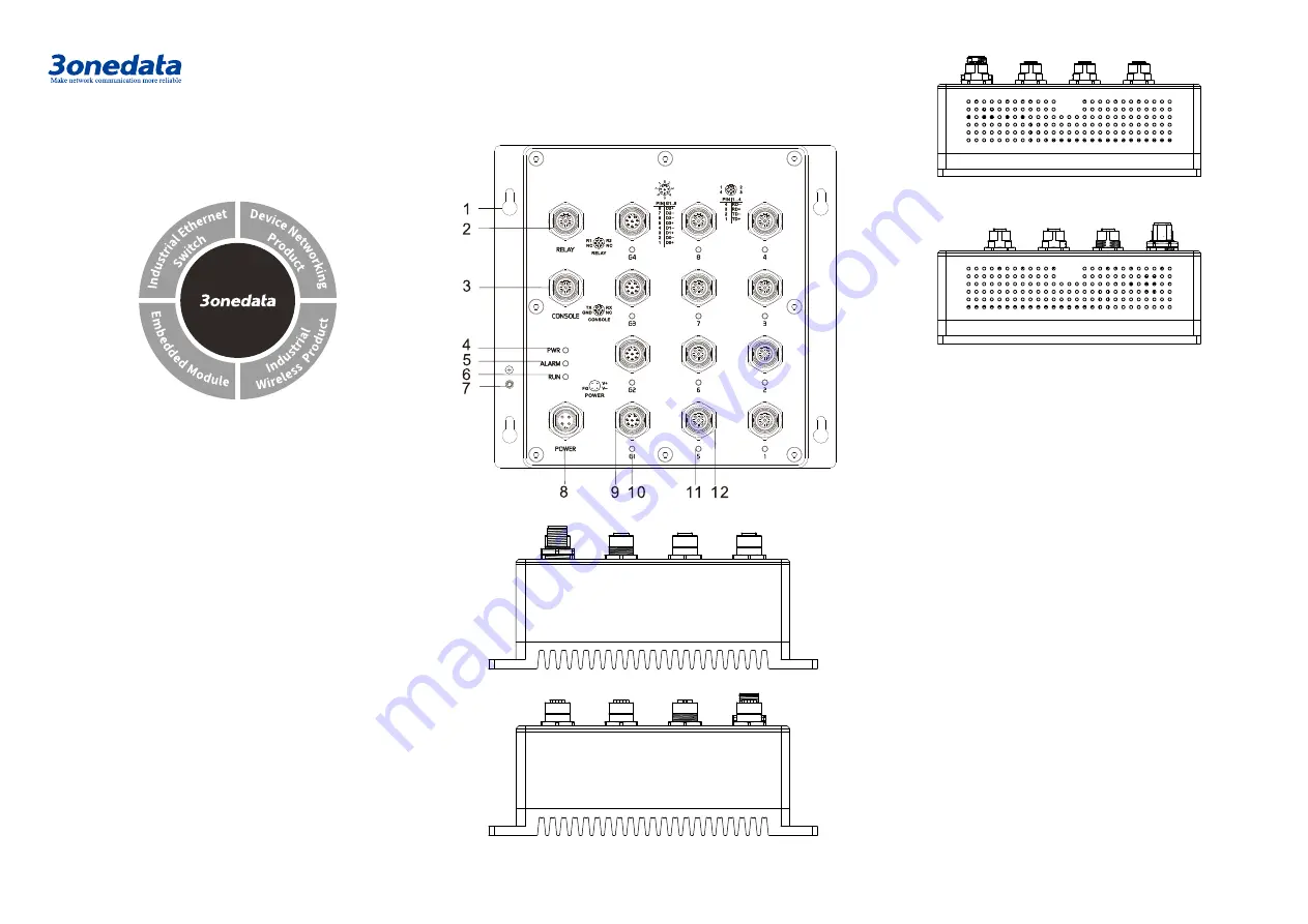
Panel Design


Front view 


Bottom view 


Top view 


Left view 


Right view 


1. 

Hanger 

2. 

Relay alarm output terminal block 

3. 

Console port 

4. 

Indicator of power supply input status PWR 

5. 

Relay alarm indicator ALARM 

6. 

Indicator of device running status RUN 

7. 

Grounding screw 

8. 

Power input terminal block 

9. 

10/100/1000Base-T(X) Gigabit copper port 

10. 

Gigabit copper port connection indicator 

11. 

100M copper port connection indicator 

12. 

10/100Base-T(X) 100M copper port 

Mounting Dimension


Unit: mm 

Address: 

3/B,  Zone  1,  Baiwangxin  High  Technology 

Industrial 

Park, 

Xili, 

Nanshan 

District, 

Shenzhen 

Website: 

www.3onedata.com 

Tel: 

+86 0755-26702688 

Fax: 

+86 0755-26703485 

Summary of Contents for TNS5800D Series

Page 1: ...ed for rail transit industry The module is TNS5800D 4GT 8T 4 Gigabit copper ports 8 100M copper ports Panel Design Front view Bottom view Top view Left view Right view 1 Hanger 2 Relay alarm output terminal block 3 Console port 4 Indicator of power supply input status PWR 5 Relay alarm indicator ALARM 6 Indicator of device running status RUN 7 Grounding screw 8 Power input terminal block 9 10 100 ...

Page 2: ...emale Power supply range 110VDC 70 160VDC The pin definitions of M12 Male are as follows No 1 2 3 4 Definition FG V V NC Description Ground Power input negative Power input positive reserved Relay Connection This device provides 1 M12 D Coded 4 Pin slot female for relay output R1 and R2 is a pair of normally open contacts of device alarm relay They are open circuit in normal non alarm state closed...

Page 3: ...N ON The device is powered on or the device is abnormal OFF The device is powered off or the device is abnormal Blinking Blink 1 time s system is running well Link Act 1 8 G1 G4 ON Ethernet port connection is active Blinking Data transmitted OFF Ethernet port connection is inactive Logging in to WEB Interface This device supports WEB management and configuration Computer can access the device via ...

Page 4: ...output M12 D coded port Indicator Power indicator run indicator interface indicator alarm indicator Exchange attributes Backplane bandwidth 128G Packet buffer size 12Mbit MAC table size 16K Power supply Input power supply 110VDC 70 160VDC M12 A coded port Consumption No load 14 30W 110VDC Full load 14 85W 110VDC Working environment Working temperature 40 75 Storage temperature 40 75 Working humidi...

Reviews: