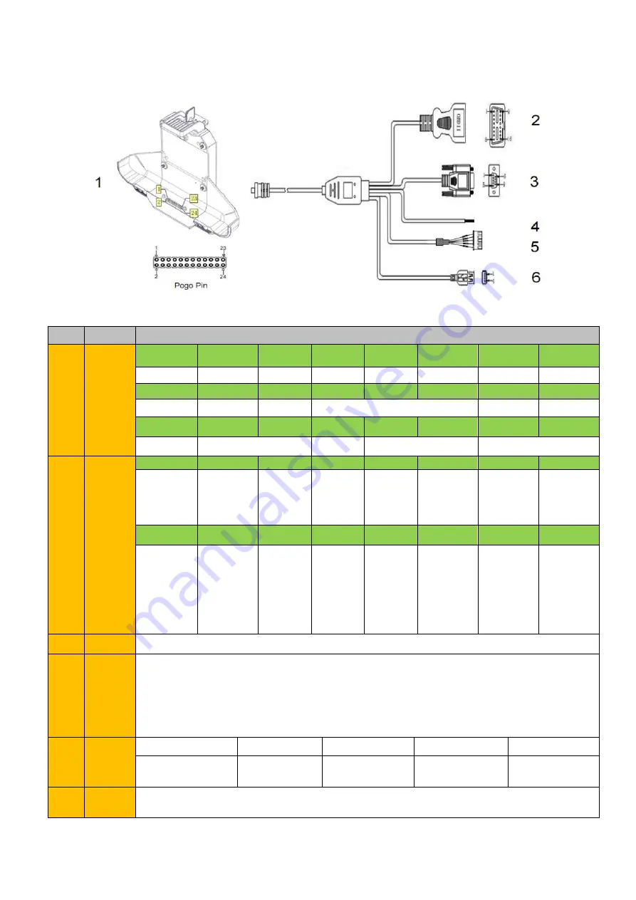
1.3.2 OBD-II Version
NO.
Item
Definition
1
Pogo
Pin
1
2
3
4
5
6
7
8
GPIO69
GPIO33
GPIO66
GPIO22
GPIO23
ACC
GND
RXD0
9
10
11
12
13
14
15
16
TXD0
RXD1
TXD1
GND
ID
DP
17
18
19
20
21
22
23
24
DM
VUSB
EN
DC+
DC-
2
OBD-II
1
2
3
4
5
6
7
8
Reserved
Bus posi-
tive line of
SAE J1850
Reserved
Chassis
ground
Signal
ground
CAN_H
line of ISO
15765-4
K_line ac-
cording to
ISO 9141-
2 and ISO
14230-4
Reserved
9
10
11
12
13
14
15
16
Reserved
Bus nega-
tive line of
SAE J1850
Reserved
Reserved
Reserved
CAN_L line
of ISO
15765-4
L_line ac-
cording to
ISO 9141-
2 and ISO
14230-4
Permanent
positive
voltage
3
COM
RS232 /dev/ttyHSL0.
4
ACC
input
Connect with vehicle ACC power.
Voltage range: 0-30V.
Note: With ACC function, the device is requested to connect the power source via DC
adaptor simultaneously to power on after ignition. please refer to 3-2 for the DEMO and
source code of ACC.
5
GPIO
Red
White
Green
Yellow
Black
Input 1
Input 2
Output 3
Output 4
GND
6
USB
USB Type-A(can not be used simultaneously with USB Type-C on the device)


