


11
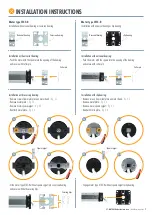
Left installation
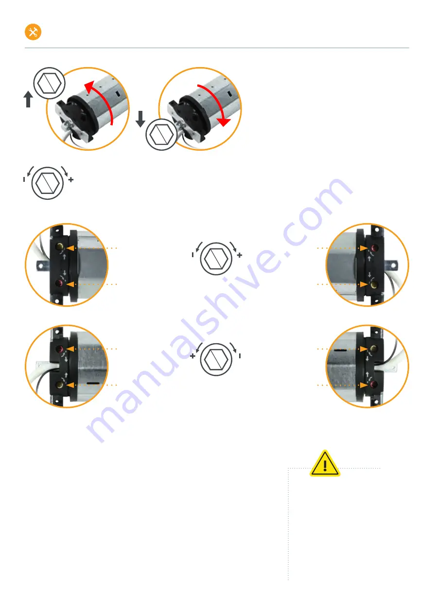
The arrows with PLUS and MINUS apply to both limit switch screws and show you in which direction you must turn the adjusting pin to switch
off the motor sooner or later. Turning the limit switch screw in the PLUS direction after switching off allows the motor to continue moving step
by step in the corresponding direction. Turning the limit switch screw in the MINUS direction during travel causes the motor to switch off earlier.
For motor type 3T45-R / power cable to the front, the PLUS and MINUS directions change (see marking on the motor head).
The straight up and down arrows indicate the direction of rotation
of the motor and shaft and thus show you for which end position
the limit switch screw next to it is responsible. Depending on
whether the direction of rotation leads to unrolling or rolling up of
the roller shutter, the limit switch screw is responsible for the lower
or upper end position (unrolling > lower end position, rolling up >
upper end position).
Special case: Roller shutter rolls down in front of motor + shaft
If the roller shutter curtain rolls in front of the motor and shaft, the responsibilities of the limit switch screws for the upper and lower end positions are reversed.
See illustration of left-right installation: upper end position > lower end position / lower end position > upper end position.
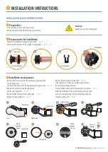
1. Setting the lower end position
•
Do not fasten the roller shutter curtain!
Detach all suspension springs from the roller shutter shaft!
•
Move the motor + shaft in the downward direction until the lower limit switch-off occurs automatically
and the motor stops.
•
Move motor + shaft upwards.
While the motor is moving upwards, turn the adjustment pin on the limit switch screw for the upper limit
position in the MINUS direction (up to 100 turns, depending on the motor type) until the motor switches
off after approx. 4 turns.
This prevents the roller shutter from being pulled out of the guide rails when the upper end position is set.
•
Move motor + shaft in downward direction to the lower end position until the motor stops automatically.
Note heat generation
The end position setting without shutter curtain
load leads to more heat generation in the
motor. This is normal behavior and does not
result in damage to the motor. If the motor
heats up too much, the thermal protection
switch of the motor is automatically triggered.
After a cooling phase of at least 10 minutes,
the motor is ready for operation again.
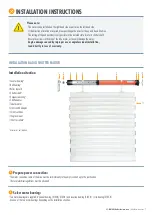
INSTALLATION INSTRUCTIONS
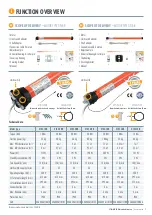
3T-MOTORS Radio tubular motors
| Installation instructions
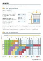
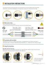
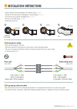
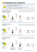
Limit switch screw white:
Lower end position
Limit switch screw red:
Upper end position
Right installation
Limit switch screw red:
Lower end position
Limit switch screw white:
Upper end position
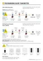
Power cable to rear
Left installation
Limit switch screw red:
Upper end position
Limit switch screw white:
Lower end position
Right installation
Limit switch screw white:
Upper end position
Limit switch screw red:
Lower end position
Power cable to front
Direction of rotation
Limit switch screw
Direction of rotation
Limit switch screw


