


13
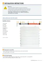
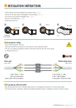
INSTALLATION RADIO AWNING MOTOR
1
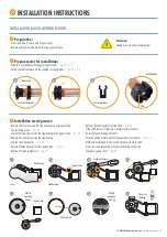
Preparation:
•
Screw in awning & secure with straps or ropes.
•
Remove awning from wall bracket & place on safe surface.
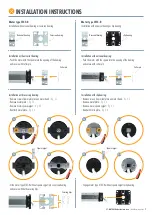
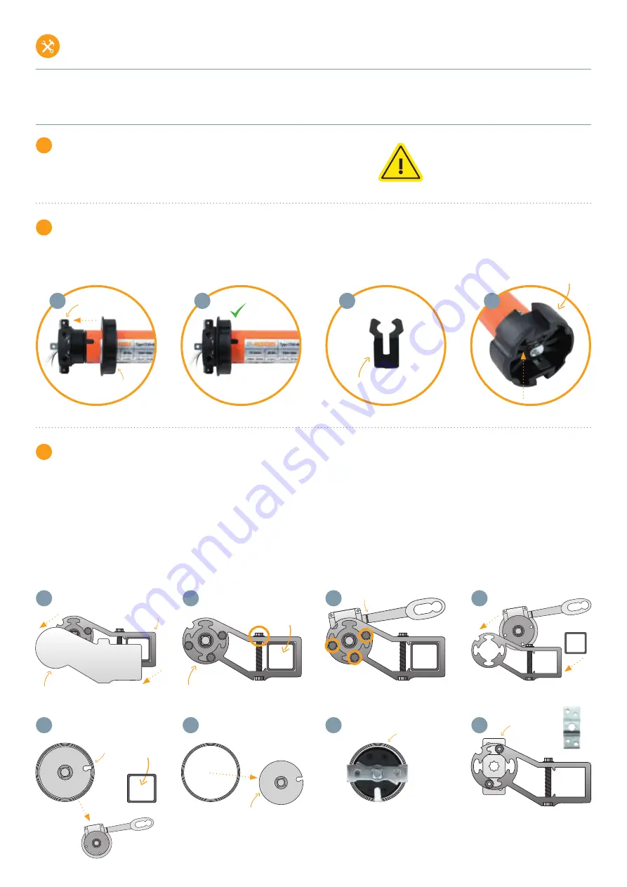
2
Prepare motor for installation:
•
Slide limit switch adapter flush against motor head.
>
fig. 2.1 / 2.2
•
Secure the shaft adapter with the supplied securing bracket.
>
fig. 2.3 / 2.4
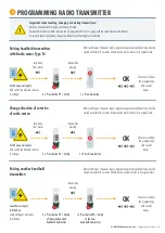
3
Installation awning motor:
•
Remove the cover to access the side bearing (also awning bracket)
and fastening screws.
>
fig. 3.1
•
Loosen the screw that secures the side bearing to the support tube.
>
fig. 3.2
•
Remove all screws connecting the side bearing
and the crank mechanism.
>
fig. 3.3
•
Remove the side bearing from the support tube.
>
fig. 3.4
•
Remove the crank mechanism.
>
fig. 3.5
Attention:
Awning arms are under strong tension!
2.1
2.2
2.3
2.4
3.1
3.2
3.2
3.4
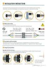
•
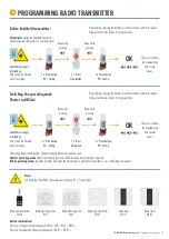
Remove the shaft capsule from the shaft.
>
fig. 3.6
If the shaft capsule is tight, use a hammer and screwdriver.
Be careful not to damage the shaft.
•
Push the awning motor with shaft adapter first into the shaft.
>
fig. 3.7
•
Make sure motor head & limit switch adapter are flush in shaft.
•
Screw the universal bearing onto the side bearing on the side
facing the awning shaft.
>
fig. 3.8
3.5
3.6
3.7
3.8
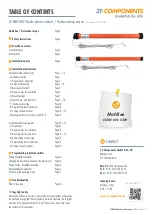
INSTALLATION INSTRUCTIONS
3T-MOTORS Radio tubular motors
| Installation instructions
Limit switch adapter
Motor head
Securing bracket
Click
Shaft adapter
Side bearing
Cover
Support tube
Side bearing
Crank mechanism
Support tube
Shaft capsule
Shaft &
wound up
Awning
Universal
bearing
Shaft &
wound up
Awning


