


16
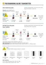
After switching on the power supply, programming (pressing the buttons) must be
carried out within 10 seconds. Otherwise the motor returns to its original state.
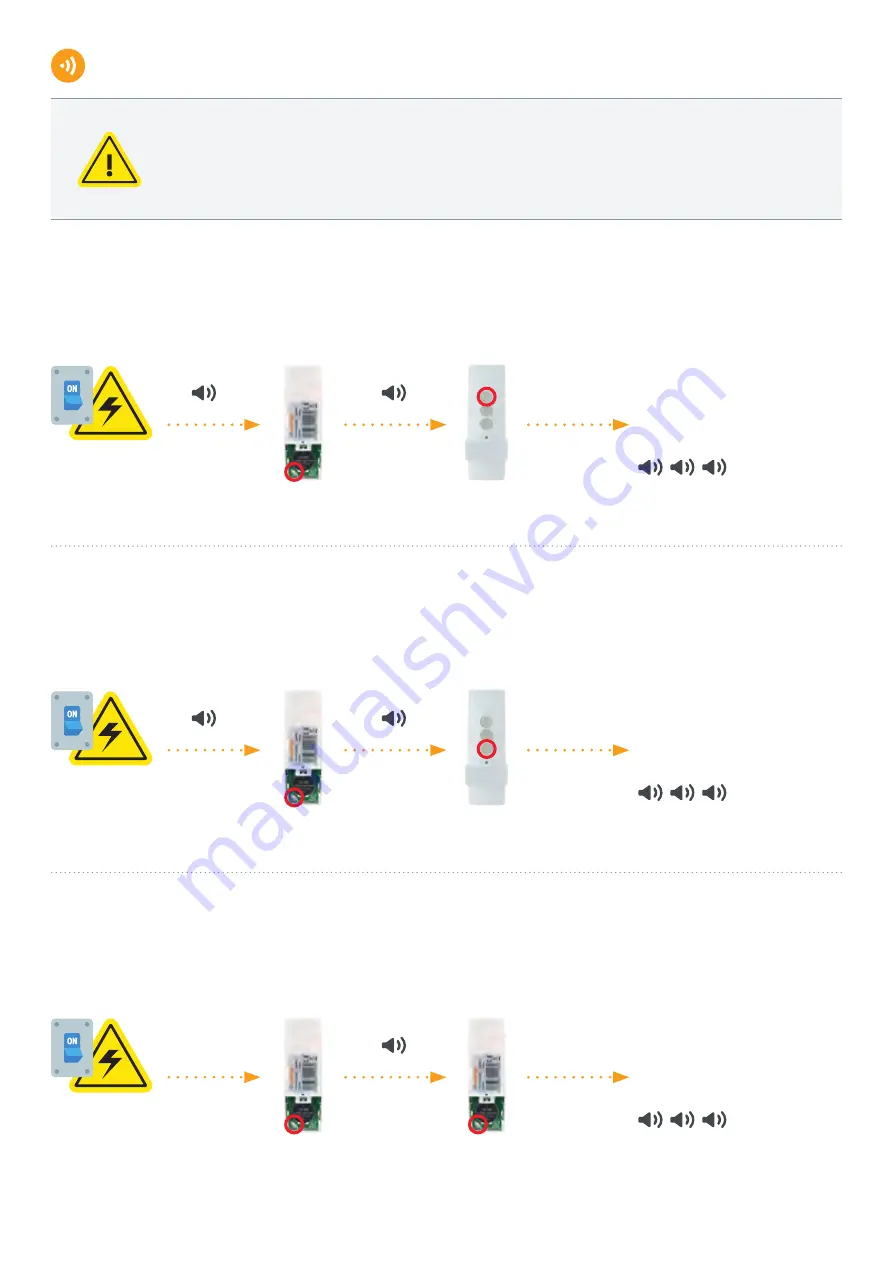
2 x Press button P2 / Set Up
of the already paired
handheld transmitter
2 x Press button P2 / Set Up
1 x Press Down-button
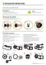
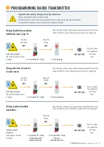
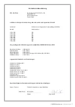
PROGRAMMING RADIO TRANSMITTER
Pairing handheld transmitters
with Radio motor Type R:
The motor confirms
the programming
with several
beeps
OK
2 x Press button P2 / Set Up
1 x Press Up-button
Beep while
pressing
Long beep
from motor
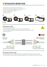
Switch on power supply.
Only switch the affected receiver
to voltage.
Change direction of rotation
of radio motor:
The motor confirms
the programming
with several
beeps
OK
Beep while
pressing
Long beep
from motor
Switch on power supply.
Only switch the affected receiver
to voltage.
Pairing another handheld
transmitter:
The motor confirms
the programming
with several
beeps
OK
1 x Press button P2 / Set Up
of the new
handheld transmitter
Beep while
pressing
Leave Power supply
switched on.
Leave voltage of all motors
switched on.
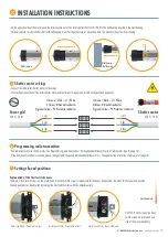
Important when teaching, changing or deleting transmitters:
Only one relevant motor may be switched to voltage!
Several radio motors or radio receivers can be programmed to form a group with the same transmission channel.
For multi-channel transmitters, channel by channel must be taught or transferred.
After switching on the power supply, programming (pressing the buttons) must be
carried out within 10 seconds. Otherwise the receiver returns to its original state.
After switching on the power supply, programming (pressing the buttons) must be
carried out within 10 seconds. Otherwise the motor returns to its original state.
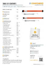
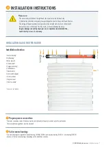
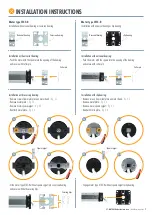
3T-MOTORS Radio tubular motors
| Programming radio transmitter


