background image

4

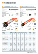
3T-MOTORS Radio tubular motors

  |  Safety instructions

GENERAL SAFETY INSTRUCTIONS

IMPROPER USE

PROPER USE

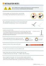
 WARNING: Important safety instructions.  

  Follow all instructions as incorrect installation may result in serious injury.

 WARNING: The drive must be disconnected from the power source during cleaning, maintenance and replacement of parts.

 Danger to life from electric shock when working on electrical equipment. 

 The electrical connection, installation and commissioning of the receiver may only be carried out by qualified personnel.  

 Before installing the drive, remove all unnecessary cables and disable all devices,  

  that are not required for operation with power.

 The relevant regulations and guidelines must be followed without fail, to avoid damage to persons and objects.

 Observe safety instructions according to EN 60 335-2-97: The power supply cable of the drives must be laid internally.

 Installation according to DIN 18073: The roller shutter box cover must be easily accessible and removable.

 Installation according to EN 60335: Only switches / pushbuttons / switching devices with a minimum contact opening 

  of 3 mm may be used, furthermore the up and down direction must be interlocked against each other.

 When installing in damp rooms, observe regulations (VDE 0100, part 701 and 702).

 These drives can be connected in parallel without an isolating relay or central control.  

  In this case, the max. output power of the command transmitter (timer or otherwise) must be observed.

 Do not use defective devices: Never use defective equipment. 

  Periodically inspect the equipment for imbalance and signs of wear or damage to cables and suspension springs. 
  Do not use equipment if repair or touch-up is necessary. 
  There is a risk of personal injury and property damage due to electric shock or short circuit.

 Retain the instructions for future reference.

 Use tubular motors only for automating shutters.

 Only use original components and original accessories from the manufacturer. 

 The mains connection cable of the drives must be laid internally in the empty conduit up to the junction box. 

  The local electrical regulations must be observed.

 For the electrical connection of the tubular motors, a 230 V / 50 Hz 

  power connection with fuse must be available at the installation site.

 Inspect the installation frequently for imbalance and signs of wear or damage to cables and springs. 

  Do not use if repairs or adjustments are required.

Please read these important safety instructions before commissioning!

Incorrect installation can cause serious personal injury and damage to property. 
The warranty claim expires in case of non-observance of this user information with all contained notes and regulations.
In case of non-observance of these instructions, the manufacturer or supplier shall not be liable for any personal injury or property damage incurred.

 SAFETY INSTRUCTIONS

This symbol indicates danger due to electrical energy. 

Danger to persons and objects may arise if the 

associated information is not observed!  

This symbol indicates information about general danger. 

Non-observance can mean danger to 

persons and objects!

This symbol indicates important information that can 

ensure safe and proper use of the device.

 Persons are to be instructed with the correct operation of the tubular motor. 

 The roller shutter movement must be monitored in order not to endanger persons. 

 Do not allow children to play with motor controls.

 Store the handheld transmitter in such a way that unintentional operation is prevented (e.g. by children playing).

 The device can be used by children aged 8 years and above and persons with reduced physical, sensory or mental 

  capabilities or lack of experience and knowledge, if they have been given supervision and instruction concerning use 
  of the appliance in a safe way and are aware of the hazards involved.

 Children are not allowed to play with the equipment.

 If the power supply cord of this device is damaged, it must be replaced by the manufacturer or its customer service 

  or a similarly qualified person to prevent hazards.

Summary of Contents for 3T-MOTORS 3T45-10R

Page 1: ...trol via smart phone tablet PC or via voice commands with Alexa or Google Assistant INTELLIGENT DRIVES CONTROLS FOR SHUTTERS AND AWNINGS INSTALLATION OPERATING INSTRUCTIONS Instructions and notes for...

Page 2: ...age 13 3 Mounting radio awning motor Page 13 14 4 Radio awning motor wiring Page 14 5 Programming radio transmitter Page 14 6 Setting the end positions Page 15 Programming radio transmitter Pairing ha...

Page 3: ...ount rail guidance of approx 10 Roller shutter area m x Weight roller shutter material m Weight roller shutter kg 10 Friction losses Required traction force kg Example PVC Roller shutter area 3 00 m x...

Page 4: ...d original accessories from the manufacturer The mains connection cable of the drives must be laid internally in the empty conduit up to the junction box The local electrical regulations must be obser...

Page 5: ...0R 10 Nm 25 kg 4 5 m 3 m 112 W 2 W 15 U min 22 230 V 615 mm 595 mm 3 m 4 min IP44 4260336110613 3T45 20R 20 Nm 40 kg 6 m 4 7 m 145 W 2 W 15 U min 22 230 V 615 mm 595 mm 3 m 4 min IP44 4260336110101 3T...

Page 6: ...Steel shafts with an internal fold will damage and destroy the motor Grinding marks of any kind on the motor housing will void the warranty The inspection cover of the roller shutter box must be easil...

Page 7: ...sal bearing 3T45 R 3T35 R and covercap bearing 3T45 R clip bearing 3T35 R Use one of the two motor bearings depending on the installation situation 1 2 3 4 5 6 7 8 9 10 11 Please note The motor can be...

Page 8: ...ips Motor type 3T35 R Installation with universal bearing or clip bearing Installation with universal bearing Push the motor with the square into the opening of the bearing and secure with cotter pin...

Page 9: ...mit switch adapter fig 4 7 4 8 5 Mount bearings Remove old wall bearing on motor side left or right installation possible Mount motor bearing at this point 2 mounting options Universal bearing and cov...

Page 10: ...dio transmitter Pair radio transmitter to shutter motor See Programming radio transmitter Pairing handheld transmitter to 3T radio motor type R page 16 If the direction of rotation is reversed please...

Page 11: ...l suspension springs from the roller shutter shaft Move the motor shaft in the downward direction until the lower limit switch off occurs automatically and the motor stops Move motor shaft upwards Whi...

Page 12: ...ternal fold the motor housing will be left with grinding marks since the suspension pin or the fold protrude too far into the roller shutter shaft Contrary to its intended use the motor runs permanent...

Page 13: ...e support tube fig 3 4 Remove the crank mechanism fig 3 5 Attention Awning arms are under strong tension 2 1 2 2 2 3 2 4 3 1 3 2 3 2 3 4 Remove the shaft capsule from the shaft fig 3 6 If the shaft ca...

Page 14: ...be changed via the radio transmitter p 16 3 9 3 10 3 11 3 12 Radio awning motor 230 V 50 Hz Power grid 230 V 50 Hz 1 brown black L1 Phase 2 blue N Neutral conductor 3 green yellow PE Protective conduc...

Page 15: ...he motor is to continue moving turn the adjustment pin on the RETURN limit switch screw in the PLUS direction until the desired position is reached and the awning is fully retracted If the awning moto...

Page 16: ...the affected receiver to voltage Pairing another handheld transmitter The motor confirms the programming with several beeps OK 1 x Press button P2 Set Up of the new handheld transmitter Beep while pre...

Page 17: ...e and vice versa Shutter operating mode Motor immediately goes into self hold when a direction button is pressed Blind operating mode Jog mode possible Only when the direction key is pressed for longe...

Page 18: ...limit switch screws 15 20 turns in the MINUS direction and set again first DOWN then UP the motor stops running after continuous operation The thermal protection switch of the motor has tripped After...

Page 19: ...e 2006 42 EG EMV Richtlinie 2014 30 EU RED Richtlinie 2014 53 EU RoHS Richtlinie 2011 65 EU Delegierte Richtlinie EU 2015 863 WEEE Richtlinie 2012 19 EU angewandte Standards und Verordnungen EN 55014...

Page 20: ...www instagram com 3tcomponents twitter com 3TComponents INTELLIGENT DRIVES CONTROLS FOR SHUTTERS AND AWNINGS Service and Quality make the difference 3T Components GmbH Co KG Bahnhofstr 34 55578 Walle...

Reviews: