


7
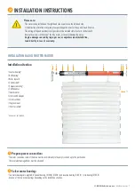
INSTALLATION RADIO SHUTTER MOTOR
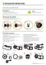
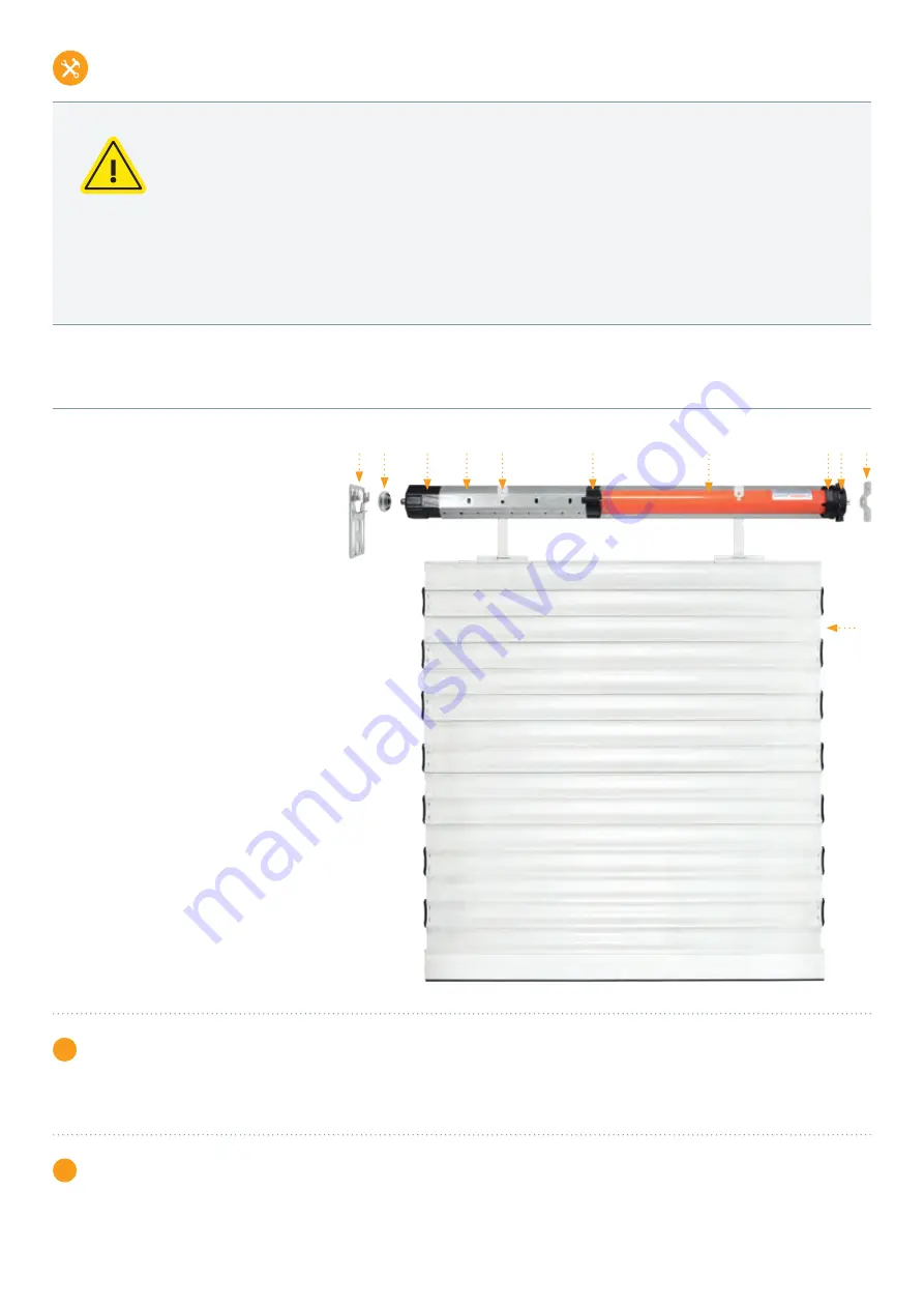
Installation situation
1
Counter bearing
*
2
Ball bearing
*
3
Roller capsule
*
4
Shutter shaft
*
5
Suspension spring
*
6
Shaft adapter
7
Tubular motor
8
Limit switch adapter
10
Limit switches
10
Engine mount
11
Shutter curtain
*
*
Accessories; not included
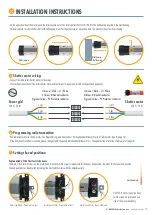
1
Prepare power connection:
•
The mains connection cable of the drive must be laid internally in the empty conduit up to the junction box.
The local electrical regulations must be observed.
2
Select motor bearing:
•
Two motor bearings are supplied: Universal bearing (3T45-R/3T35-R) and covercap bearing (3T45-R) / clip bearing (3T35-R).
•
Use one of the two motor bearings depending on the installation situation.
1 2
3
4
5
6
7
8 9 10
11
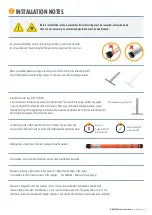
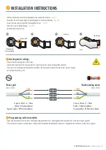
Please note:
•
The motor can be installed on the right-hand side as well as on the left-hand side.
If the direction of rotation is reversed, please exchange the wires for the up and down direction.
•
The setting of the end positions is only possible in the installed state (motor in shutter shaft).
•
Never place screws in the area of the tube motor, as they will damage the motor.
•
Engine damage caused by improper use or unprofessional installation,
lead directly to loss of warranty.
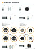
INSTALLATION INSTRUCTIONS
3T-MOTORS Radio tubular motors
| Installation instructions


