


9
3
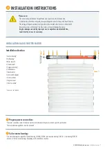
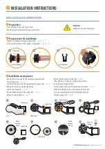
Remove shutter shaft:
•
Lower the roller shutter.
•
Open the cover of the roller shutter box.
•
Release the suspension springs from the roller shutter shaft.
•
Lift roller shutter shaft incl. ball bearing out of the holder.
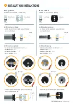
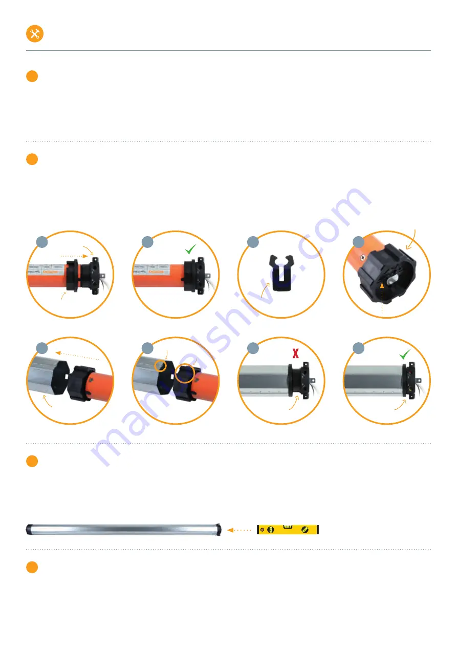
4
Prepare motor for installation:
•
Push limit switch adapter flush against motor head.
>
fig. 4.1 / 4.2
•
Secure the shaft adapter with the supplied securing bracket.
>
fig. 4.3 / 4.4
•
Push the motor into the roller shutter shaft without using force (never knock it in). The fold of the shaft must lie over the recess in the shaft adapter.
>
fig. 4.5 / 4.6
•
Make sure that the roller shutter shaft is flush with the motor head limit switch adapter.
>
fig. 4.7 / 4.8
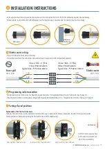
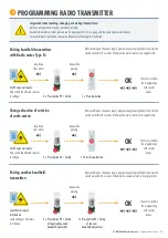
5
Mount bearings:
•
Remove old wall bearing on motor side (left or right installation possible).
•
Mount motor bearing at this point (2 mounting options: Universal bearing and cover cap bearing / clip bearing).
•
Please mount the bearings so that the limit switches are freely accessible.
•
Make sure that the roller shutter motor with the shaft unit sits horizontally in the roller shutter box.
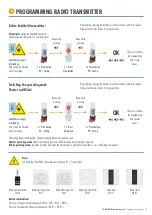
6
Mount motor with shaft unit:
•
Insert the motor head (with the entire shaft unit) into the motor bearing and secure it with the supplied cotter pin or securing clips (Cover cap bearing)..
4.1
4.2
4.3
4.4
4.5
4.6
4.7
4.8
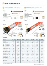
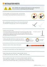
3T-MOTORS Radio tubular motors
| Installation instructions
INSTALLATION INSTRUCTIONS
Limit switch adapter
Motor head
Securing bracket
Click
Shaft adapter
Roller shutter shaft
Fold
Recess
wrong
right


