background image


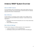
Antenna WASP System Overview 


Antenna WASP Sensors 

The antenna WASP sensors are designed with a highly sensitive digital compass and 
inclinometer to precisely measure the orientation of cellular antennas and to wirelessly 
relay the information back to the Data Collector. 


Data Collectors  

The Data Collector is an embedded computer installed at each installation site that 
receives and records antenna WASP sensor information. The Data Collector is also 
responsible for: 

  Monitoring the sensor data and raising alarms when out-of-range measurements 

are detected. 

  Generate SNMP traps (optional) 


Data Collector Manager 

The Data Collector Manager is a Windows application which is responsible for: 

  Configuring the settings in one or more Data Managers. 

  Downloading and viewing antenna WASP sensor data from Data Managers. 


Summary of Contents for Antenna W.A.S.P.

Page 1: ...Antenna W A S P User s Guide...

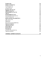
Page 2: ...LATION GUIDE 12 STEP 1 INSTALL THE DATA COLLECTOR MANAGER SOFTWARE 12 STEP 2 INSTALL THE DATA COLLECTOR 16 STEP 3 INSTALL THE DATA COLLECTOR ANTENNA 18 STEP 4 RUN THE DATA MANAGER SOFTWARE 19 STEP 5 C...

Page 3: ...3D VIEW 44 ANTENNA WASP SETTINGS 46 ANTENNA WASP IDENTIFICATION 46 TARGET ORIENTATION 46 DOWNLOADING ANTENNA WASP DATA 47 3D PLAYBACK VIEW 49 GRAPH VIEW 50 TABLE VIEW 52 EXPORTING ANTENNA WASP DATA 5...

Page 4: ...armful interference in which case the user will be required to correct the interference at his own expense Industry Canada Notifications This device complies with Industry Canada s license exempt RSSs...

Page 5: ...5 CE Mark Conformity...

Page 6: ...ense for operation Contact local authority for procedure to follow Note ESD precautions should be used when attaching or removing the antenna from the Data Collector Note Combinations of power levels...

Page 7: ...ed such that a separation of at least 20 centimeters is maintained between the Product s antenna and personnel in the vicinity of the device The antenna used for this transmitter must not be co locate...

Page 8: ...Please note that the WASP Sensor is designed to only operate with an internal non user replaceable antenna Therefore the list below is applicable only to the Data Collector List of Approved Antennas f...

Page 9: ...or is an embedded computer installed at each installation site that receives and records antenna WASP sensor information The Data Collector is also responsible for Monitoring the sensor data and raisi...

Page 10: ...and is specified in degrees offset from magnetic north This value can range from 0 degrees north to 359 degrees Roll is a measure of the sensor s deviation from level with respect to the horizon This...

Page 11: ...sor is at the limit of the wireless range or that something has moved into the transmission path and is blocking the signal This signal strength information can be configured to generate alarm conditi...

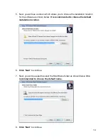
Page 12: ...n and is running Windows 7 Windows 8 1 or Windows 10 To install the software on your Windows system please do the following 1 Open Windows Explorer and locate the Data Collector Manager Installer file...

Page 13: ...on location for the software as shown below It is recommended to choose the default installation location 6 Click Next to continue 7 Next you will be asked to select the Start Menu folder as shown bel...

Page 14: ...reate a desktop icon for the Data Collector software as shown below 10 Click Next to continue 11 Finally you will be prompted to confirm the installation details with a window similar to the one shown...

Page 15: ...taller will then install the Data Collector Manager software onto your Windows computer When it is finished you will be prompted with a completion screen as shown below 13 Click Finish to complete the...

Page 16: ...te connectivity connect a standard CAT5 with RJ45 connector from the Ethernet port to router Make 2 loops of the Ethernet cable around ferrite core Fair Rite 0446167251 1 and secure the cable loops by...

Page 17: ...er source of the Data Collector is 48VDC supplied by a power source at the base of the tower The Data Collector does not require connections at the two USB Ports nor the Power Jack 5 12V to operate No...

Page 18: ...n below The antenna must be installed with direct line of sight to the Antenna WASP sensors installed on the antennas WARNING Always be aware of power lines and ensure this antenna is installed at lea...

Page 19: ...at was installed in Step 1 by clicking on the 3z Telecom Data Collector Manager application A login prompt will appear as shown below Enter your username and password and click Login When you have suc...

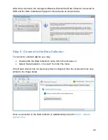
Page 20: ...the Data Collector To connect to a Data Collector you may Double click the Data Collector s name link in the left pane or Select Data Collector Connect from the File menu If the Data Collector has not...

Page 21: ...Ensure the clock on the PC running the Data Collector Manager software is set to the correct time and time zone 2 Click on the Data Collector Site Name in the left pane to select the Data Collector 3...

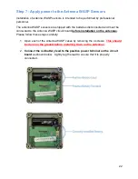
Page 22: ...st be connected to the Antenna WASP circuit board before installation on the antennas Please follow these steps carefully 1 Open each of the Antenna WASP cases by removing the 4 screws This should be...

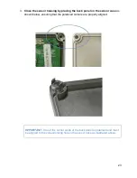
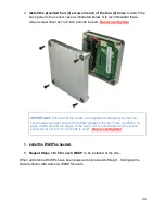
Page 23: ...panel on the sensor case as shown below ensuring that the polarized corners are properly aligned IMPORTANT One of the corner posts of the back panel is polarized and must be aligned to the correspond...

Page 24: ...are tightened sufficiently so that the case makes a proper seal to the rubber gasket in the lid There should be no gaps visible around the edges of the case It is recommended that a torque screw driv...

Page 25: ...rting position information To configure the Data Collector with new WASP sensor information do the following 1 Click the Add Remove Antenna WASP link in the left pane of the manager window and the con...

Page 26: ...tenna WASP on the label on the side of the case as shown below 4 Enter the MAC Address of the Antenna WASP from the label into the top field as highlighted below Note this address can only contain hex...

Page 27: ...as shown below Note The sector and antenna name are fields which will be used to uniquely identify the sensor and corresponding antenna on which it is installed 6 Enter the Target Orientation for the...

Page 28: ...to 180 degrees c Roll specifies the side rotation of the antenna 180 to 180 degrees For more information on these orientation values refer to the section titled 3 D Orientation Azimuth Tilt and Roll o...

Page 29: ...a prompt to confirm the changes similar to the one shown below 10 Carefully review the changes and then click Yes to save the configuration to the Data Collector When all Antenna WASPs have been prope...

Page 30: ...step each of the antenna WASP sensors must connect to the Data Collector and report position information When the sensors are connected the status information will appear with a green icon next to eac...

Page 31: ...r The following steps must be followed precisely to ensure the Antenna WASPs are securely fastened onto the antennas 1 Clean the area where the Antenna WASP is to be mounted with a rag and clean water...

Page 32: ...s shown below IMPORTANT The Antenna WASP must be installed such that the arrow etched into the case points upward towards the sky 6 Repeat steps 1 5 for each antenna When all WASP Remotes have been in...

Page 33: ...emotes Now that the antenna WASP sensors are properly installed on the antennas and connected to the Data Collector each sensor must be commissioned Please follow these steps for each antenna WASP sen...

Page 34: ...the left pane to return to the summary screen 6 Wait at least 5 minutes for each antenna WASP sensor to report position information to the Data Collector 7 When each antenna WASP sensor is properly i...

Page 35: ...software by clicking on the 3z Telecom Data Collector Manager application from the list of installed programs in Windows A login prompt will appear as shown below Enter your username and password and...

Page 36: ...anager software is running it starts automatically scanning for Data Collectors on USB or Ethernet When a Data Collector is discovered it will automatically appear in the left pane as shown below This...

Page 37: ...not previously been configured then no antenna WASP sensors will appear and you will need to follow the step by step instructions in the Antenna WASP Installation Guide on page 12 to ensure the system...

Page 38: ...the one shown below will automatically appear in the right pane This summary view provides a quick overview of the status of an entire antenna WASP installation and allows administrators and technicia...

Page 39: ...n the Data Collector s Site Name in the Data Collector s status summary 2 Click on the General Settings tab in the right pane This will make the General Settings panel appear as shown below NOTE Once...

Page 40: ...ings The alarm settings page allows the user to configure the thresholds for several measured parameters which define when the Data Collector generates an alarm condition The following describes each...

Page 41: ...to a Local Area Network LAN if available Host Name This specifies the hostname of the Data Collector as used in name resolution If unsure use the default value Use DHCP to obtain IP Address If this o...

Page 42: ...ttings for SNMP Inform messages Trap Host specifies the destination and settings for SNMP Trap messages Both of these host fields follows the same basic format host community port Host specifies the S...

Page 43: ...d Sensor Measurements on page 10 for a description of each field in the Measurements and Wireless Signal Strength sections The Antenna WASP Information section lists additional information specific to...

Page 44: ...left pane 2 Click on the 3D View tab in the right pane The 3D view for the WASP sensor will appear in the right pane It will be similar to the following This view renders a virtual beam in red to dis...

Page 45: ...istance this slider controls the distance from the virtual antenna and will zoom in and out as the slider is moved to the left and right respectively Vertical Angle this slider controls the virtual al...

Page 46: ...entification The identification of each WASP sensor is broken into two fields Sector Name indicates the sector azimuth of the cellular antenna on which the WASP sensor is installed Antenna Name unique...

Page 47: ...nsors 1 Click on the Data Collector s Site Name in the left pane 2 Click on the Graph View or Table View tab in the right pane To download and view data for a single WASP sensor 1 Click on the icon fo...

Page 48: ...eported before the date and time specified in the corresponding date time field to the right Only Alarms you can further narrow the search to report only sensor data which caused an alarm condition in...

Page 49: ...The playback can be controlled using the controls immediately below the 3D view Press the Play button to start the playback When playback is running you can click the Stop button to stop the playback...

Page 50: ...in a window similar to the image below The Display Filter allows you to choose which traces will be automatically plotted on the graph to the right as highlighted above By default the chart will displ...

Page 51: ...so to view more detailed information in the chart view you can hover the mouse over a specific data point and the specific measurement data will appear automatically in a popup message as illustrated...

Page 52: ...y filters and data page controls operate in the same manner as described in the section titled Graph View on page 51 Exporting Antenna WASP Data Any data which has been downloaded to the manager softw...

Page 53: ...collector Although this information is also available in the standard graph view the data in this graph is recorded in 15 minute intervals as opposed to the standard hourly interval This allows the u...

Page 54: ...ble The data in this table is directly related to the data in the temperature graph discussed in the previous section This data can be exported using the Export to CSV button found at the top right co...

Page 55: ...ors as well as alarm events If for any reason the user suspects that the system is not functioning optimally this should be the first place to look for possible causes To view system history do the fo...

Page 56: ...56 Each event is marked with the UTC time as well as the Local time The type of event is also shown followed by a brief description Alarms are shown in red...

Page 57: ...the System tab in the right pane This will make the system status summary appear as shown below The above image is from a Data Collector which is operating correctly as indicated by The green Operati...

Page 58: ...g By default the Data Collector Manager software will not automatically refresh the display which means you must click the Refresh button in order to update the display However if you check the automa...

Page 59: ...59 Technical Support Contacts...

Reviews: