background image

Building Instructions for 4-Max SpinRay 

This design and all information contained in these building instructions are the © Copyright of 4-Max. 

4-Max can not responsible for any damage or injury caused by this flying model. 

www.4-Max.co.uk 


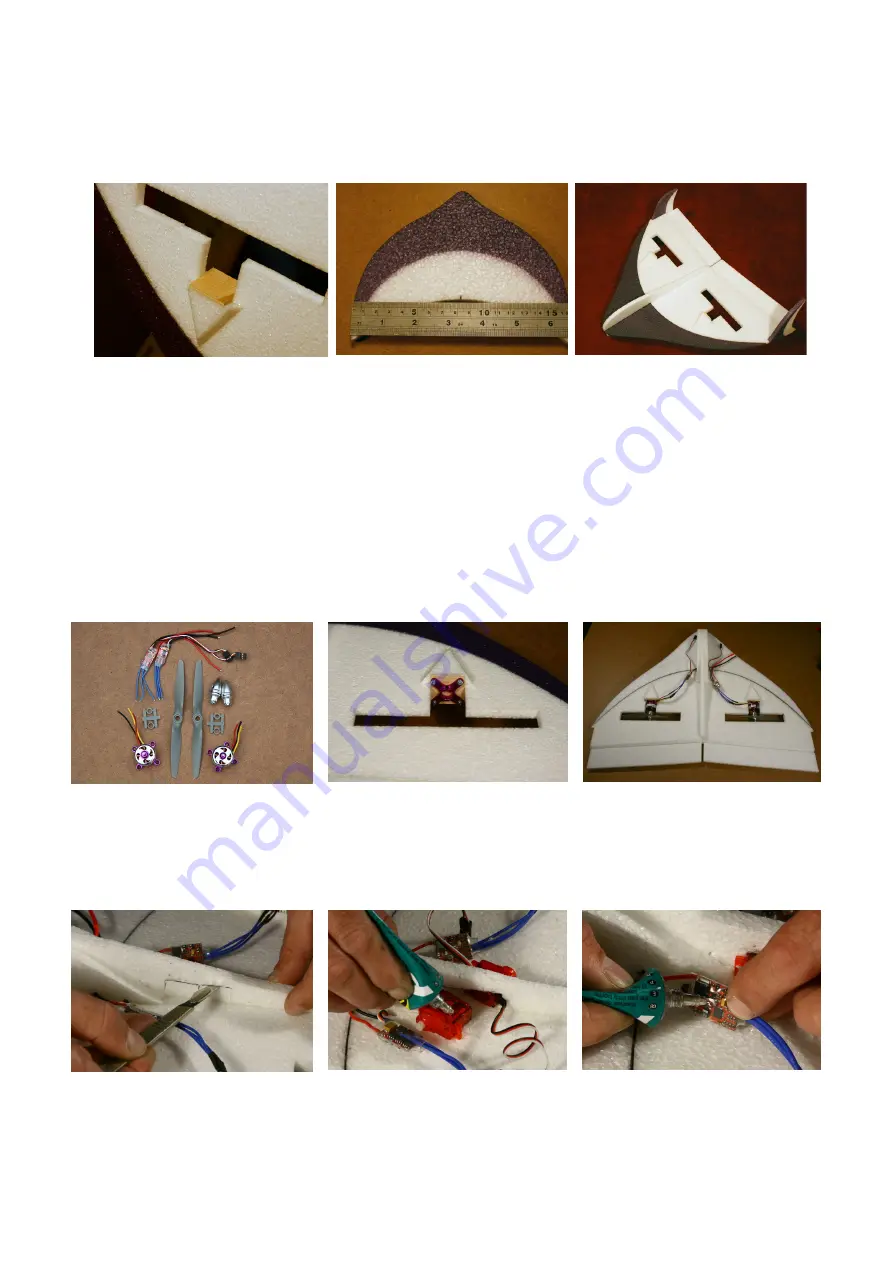
Motor Mounts and Side Fins 


Glue the light ply motor 

mount to the wing as per 

photo (contact glue style). 

The light ply mount is slightly 

oversized, this is intended. 


Measure the centre of the 

side fins and glue to wing 

(contact glue style) ensuring 

they are square from the 

front and side 

The finished model 


We find it’s easier to install the motors, ESC’s, Servo’s and Receiver before adding the side 
fins. 


The Following Only Applies If You Are Installing The 4-Max 
Power Package 


The 4-Max Power Package 


Mark and pilot drill the holes 

for the motor mount. Add a 

small drop of thin cyano to the 

holes to strengthen the light 

ply. Install the motor mount as 

in the picture. 

Motors and ESC’s installed. 


Mark and cut out the hole for 

the servos 

Use UHU Por to tack the servos 

in place 

Use UHU Por to tack the ESC’s 

and wires in place 


Summary of Contents for SpinRay

Page 1: ...ormation contained in these building instructions are the Copyright of 4 Max 4 Max can not responsible for any damage or injury caused by this flying model www 4 Max co uk Building Instructions www 4...

Page 2: ...mmend Purple Power PPB 2826 1400 2 x 10A 12A Electronic Speed Controllers 2 x Prop Adapters 1 x 6x4 APCE Prop standard rotation 1 x 6x4 APCE Prop opposite rotation 1 x 3S 740mAh or 800mAh LiPo battery...

Page 3: ...wing and allow to dry for 20 minutes Leave a 2 3mm gap at the wing tip Do not make the elevons flush to the end of the wings as this will interfere with the movement of the elevons against the side f...

Page 4: ...4 Max co uk Lower Fuselage Apply a generous amount of UHU Por to one side of the lower fuselage side cheek and join to the long main fuselage and gently move parts in a circular motion to ensure glue...

Page 5: ...Apply a thin layer on one side of the carbon spar Allow to cure for 10 15 minutes before joining contact glue style Spread a thick layer of UHU Por to the curved trailing edge of the front part of the...

Page 6: ...fins and glue to wing contact glue style ensuring they are square from the front and side The finished model We find it s easier to install the motors ESC s Servo s and Receiver before adding the sid...

Page 7: ...nut and then spray with kicker Ensure that the wire retainer can rotate easily Mark the position for the horn ensuring the holes are over the hinge line as in the above photo Use a 2mm drill to drill...

Page 8: ...ng the battery fore and aft Mark and cut the hole for the battery Slightly undercut the hole to ensure a snug fit for the battery The finished model all wired up and ready to fly after a bit of progra...

Reviews: