

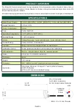


STANDARD WIRING DIAGRAM
All wiring must be In accordance with local and national electrical codes and should be undertaken by
an experienced and qualified electrician.
Always use dust/liquid tight flexible metal conduit with approved fittings to protect the sensor cables.
Use rigid metal conduit to protect the cables from the sensors to the control unit. Conduit systems can
channel water due to ingress and condensation directly to sensors and sensor connections which over
time will adversely affect the performance of the system. As such, the installation of low point conduit
drains is recommended for all sensors.
SENSOR CALIBRATION
1. The unit must be installed before calibration takes place, connect the Binswitch to power and a
suitable control unit
2. Check that no material is around the tip of the Binswitch
3.
Carefully turn the calibration control screw fully counterclockwise until red LED is “ON”. This will set
the sensor sensitivity to zero.
4. With no material around the tip of the Binswitch, rotate the control screw clockwise until the LED
goes “OFF”. Then slowly rotate the control screw counterclockwise until the LED goes “ON”.
Finally, to set the sensor sensitivity to the optimum setting, turn the control screw ten degrees
counterclockwise.
5.
Start the process to cover the Binswitch with material and check that the red LED goes “OFF” and
that the Binswitch shuts down the equipment as required.
6.
Remove the material from the Binswitch and check that the red LED comes “ON” and that the
Binswitch operates the equipment as required.
7. The Binswitch is now set and ready for use.
PAGE 8
WARNING
If the material being monitored creates dust, you may need to re-calibrate the sensor. Dust build up
on the Binswitch will affect the initial calibration. Do
NOT
remove the Binswitch and clean off the
dust. To adjust the sensor to the dust build up, turn the control screw slowly counterclockwise until
the LED turns “ON”.
Always check that the Binswitch detects material after the sensitivity has been adjusted.
NOTE
The total sensitivity setting of the control screw is four full rotations (clockwise and counterclockwise).
To prevent damage to the control screw, the screw will continue to rotate after four full rotations.
Turning the control screw counterclockwise decreases the sensor sensitivity, turning clockwise
increases the sensitivity.
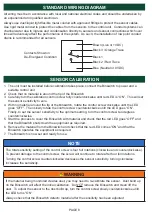
Brown (Live or +VDC)
Black 3 / Orange Trace
Black 1
Black 2 / Red Trace
Blue (Neutral or 0VDC)
Contacts Shown in
De-Energized Condition
Summary of Contents for Binswitch BS1V3FC
Page 2: ......


