


PAGE 13
Black
Brown
Black
Brown
Black
Brown
Black
Brown
Bearing
Bottom (Tail)
Bearing
Top (Head)
RIGHT
LEFT
RIGHT
LEFT
Blue
Black
Speed
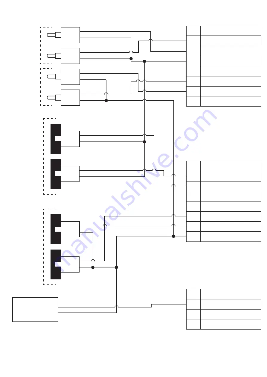
8.4 STANDARD SENSOR WIRING DIAGRAM:
- MILLI-TEMP (BEARING TEMP), RUB BLOCKS (BELT ALIGNMENT) & MILLI-SPEED (SPEED)
01
0 VDC
02
CLI#1
03
CLI#2
04
+24 VDC (Fuse F1)
05
0 VDC
06
CLI#3
07
CLI#4
08
+24 VDC (Fuse F2)
09
0 VDC
10
CLI#5
11
CLI#6
12
+24 VDC (Fuse F3)
13
0 VDC
14
CLI#7
15
CLI#8
16
+24 VDC (Fuse F4)
17
0 VDC
18
CLI#9
19
CLI#10
20
+24 VDC (Fuse F4)
Yellow
Red
Orange
Yellow
Red
Orange
Alignment
Top (Head)
Black
Brown
Black
Brown
Alignment
Bottom (Tail)
Black
Brown
Black
Brown
RIGHT
LEFT
RIGHT
LEFT
Blue
Brown
Brown
Blue
White
Summary of Contents for IE-NODE 2
Page 23: ...PAGE 23 END USER NOTES...
Page 24: ...END USER NOTES PAGE 24...
Page 25: ...END USER NOTES PAGE 25...
Page 26: ...PAGE 26 END USER NOTES...


