background image

PAGE 14

8.5 INDIVIDUAL BEARING SENSOR WIRING DIAGRAMS:

Black

Brown

0 VDC

CLI#

+24 VDC

Milli-Temp 4-20 mA

8.6 INDIVIDUAL BELT ALIGNMENT SENSOR WIRING DIAGRAMS:

0 VDC

CLI#

+24 VDC

Black

Brown

4-20 mA Rub Block (Milli-Temp)

8.7 INDIVIDUAL SPEED SENSOR WIRING DIAGRAMS:

Blue

Black

Speed

0 VDC

CLI#

+24 VDC

Milli-Speed (4-20 mA)

Summary of Contents for IE-NODE 2

Page 1: ...DE 2 10 ANALOG 4 20 mA INPUTS COMMUNICATION PROTOCOLS PROFINET ETHERNET IP MODBUS TCP IP INSTALLATION INSTRUCTIONS OPERATION MANUAL Part No s ETH NODE2V46CAI ETH NODE2V4CAI Hardware Version R3 Softwar...

Page 2: ...rts will cause severe injury or death Lockout power before removing cover or inspection door DANGER DANGER Moving parts can crush and cut Lockout power before removing guard or servicing Do NOT operat...

Page 3: ...Page 14 8 6 Individual Belt Alignment Sensor Wiring Diagrams Page 14 8 7 Individual Speed Sensor Wiring Diagrams Page 14 9 IE NODE OPERATION Page 15 16 9 1 Startup Operation Page 15 9 2 Rotary Switch...

Page 4: ...onal Electrical Codes and other standards applicable to your industry Please see the article Hazard Monitoring Equipment Selection Installation and Maintenance at www go4b com The installation of the...

Page 5: ...ation animal or insect infestation and the real world experience of knowing how your employees perform their jobs The personnel or person you select to install operate maintain inspect or perform any...

Page 6: ...face temperature monitoring is desired or required PAGE 6 3 SPECIFICATIONS Supply Voltage 120 to 240 VAC ETH NODE2V46CAI 24 VDC ETH NODE2V4CAI Power Dissipation 12 Watts Maximum Sensor Supply 24 VDC 8...

Page 7: ...E Special Consideration when installed in a Class II environment Power input and output I O wiring shall be in accordance with Class II wiring methods per the National Electrical Code NFPA70 for insta...

Page 8: ...ch end of the drive and tail or head and boot shafts BELT MISALIGNMENT Qty 4 Sensors work in pairs one for each side of the belt on the drive and tail or head and boot sections TAIL PULLEY MISALIGNMEN...

Page 9: ...ble metal conduit with approved fittings to protect the sensor cables Use rigid metal conduit to protect the cables from the sensors to the control unit Conduit systems can channel water due to ingres...

Page 10: ...ensor Input 07 CLI 4 Sensor Input 08 24 VDC Fuse F2 09 0 VDC 10 CLI 5 Sensor Input 11 CLI 6 Sensor Input 12 24 VDC Fuse F3 13 0 VDC 14 CLI 7 Sensor Input 15 CLI 8 Sensor Input 16 24 VDC Fuse F4 17 0 V...

Page 11: ...PAGE 11 8 WIRING DIAGRAMS 8 1 SUPPLY VOLTAGE WIRING 120 TO 240 VAC 21 22 23 24 No Connection N L Ground Fuse 2 A 8 2 SUPPLY VOLTAGE WIRING 24 VDC 21 22 23 24 No Connection Ground 24 VDC Fuse 2 A...

Page 12: ...D DRIVE BOOT TAIL Hot Bearing Sensor Hot Bearing Sensor Hot Bearing Sensor Hot Bearing Sensor Alignment Top Right Alignment Top Left Alignment Bottom Left Alignment Bottom Right Speed Sensor INDUSTRIA...

Page 13: ...ILLI SPEED SPEED 01 0 VDC 02 CLI 1 03 CLI 2 04 24 VDC Fuse F1 05 0 VDC 06 CLI 3 07 CLI 4 08 24 VDC Fuse F2 09 0 VDC 10 CLI 5 11 CLI 6 12 24 VDC Fuse F3 13 0 VDC 14 CLI 7 15 CLI 8 16 24 VDC Fuse F4 17...

Page 14: ...lack Brown 0 VDC CLI 24 VDC Milli Temp 4 20 mA 8 6 INDIVIDUAL BELT ALIGNMENT SENSOR WIRING DIAGRAMS 0 VDC CLI 24 VDC Black Brown 4 20 mA Rub Block Milli Temp 8 7 INDIVIDUAL SPEED SENSOR WIRING DIAGRAM...

Page 15: ...firmware or hardware On Normal operation no external communications from a PLC or other device Flashing Normal operation external communication detected from a PLC or other device Fading Bootloader mo...

Page 16: ...C temperature sensor This device is mounted to the IE NODE PCB and will therefore provide the temperature of the electronics If an IE NODE is mounted in the field it could be used to approximate the l...

Page 17: ...NET and EtherNet IP array type communications The Ethernet Node also has an FTP server This should only be used for firmware updates User should not use this FTP server to store any files as it may be...

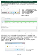
Page 18: ...a different network card than the one selected you can change the selection in the drop down menu and select Update List If you add or remove a network device after the software is opened you can sel...

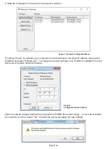
Page 19: ...nd select Refresh List To change the network settings of an IE NODE highlight it from the device list and select Network Settings Enter the network changes followed by the password BBBB then select Ap...

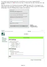
Page 20: ...node s IP address into a web browser Enter the user name root followed by the password BBBB then select OK Once logged in you will be taken to the home page on the web server Click on Network Settings...

Page 21: ...of the IE NODE by selecting Update ID Note that this ID will only be used if dipswitch 8 is in the ON Right position Otherwise the rotary switch will override the address in memory Unless instructed b...

Page 22: ...2 Make sure there is no water damage to the inside of the node or any junction boxes used 3 Verify that the configuration switches of the IE NODE are set as intended 4 Verify that the LED marked HB i...

Page 23: ...PAGE 23 END USER NOTES...

Page 24: ...END USER NOTES PAGE 24...

Page 25: ...END USER NOTES PAGE 25...

Page 26: ...PAGE 26 END USER NOTES...

Page 27: ...E OR MISAPPLICATIONS AS AUTHORIZED BY LAW 4B SPECIFICALLY DISCLAIMS ALL WARRANTIES THAT THE PRODUCT IS FIT OR MERCHANTABLE FOR A PARTICULAR PURPOSE 3 NO WARRANTY BY SAMPLE OR EXAMPLE ALTHOUGH 4B HAS U...

Page 28: ...Street Acacia Ridge Queensland 4110 Australia Tel 61 0 7 3216 9365 Email 4b australia go4b com 4B COMPONENTS LTD 625 Erie Avenue Morton IL 61550 USA Tel 309 698 5611 Fax 309 698 5615 4B BRAIME COMPON...

Reviews: