


PAGE 15
9. IE-NODE OPERATION
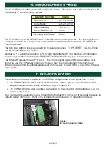
The Industrial Ethernet Node is designed to sample data from several sensors and provide this data to
remote users or PLC’s on request. It is only a reporting system, and does not control any other system
or device.
9.1 STARTUP OPERATION -
After all sensor and power connections have been made, locate the POWER and HB (Heart Beat)
LED’s on the IE-NODE’s control board (See Image 1). When the unit is powered on, the red power LED
should be solid and the green HB LED should begin flashing.
The HB LED will behave in one of four ways -
HB LED
DESCRIPTION
Off
No internal communications, indicates an issue with the firmware or hardware.
On
Normal operation, no external communications from a PLC or other device.
Flashing
Normal operation, external communication detected from a PLC or other
device.
Fading
Bootloader mode (allows for software updates)
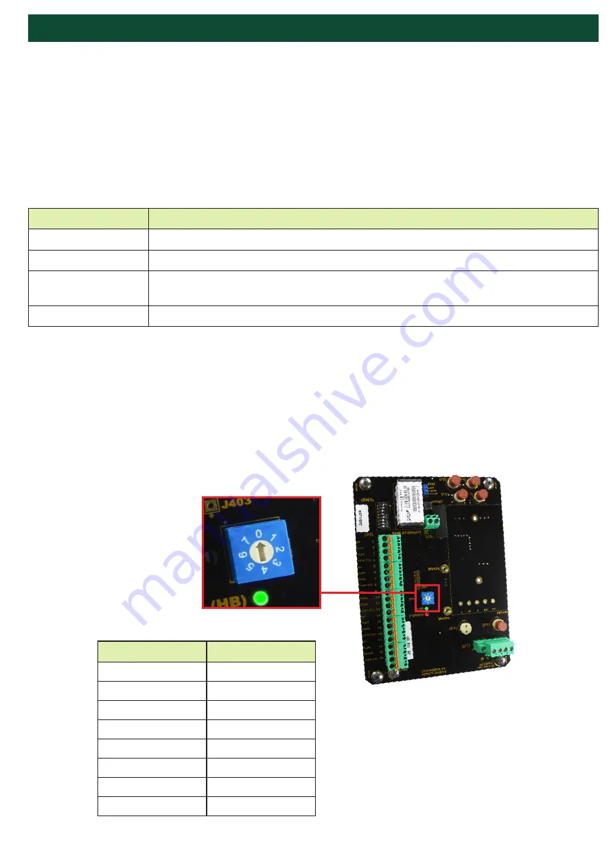
9.2 ROTARY SWITCH (SW1) -
The rotary switch on the IE-NODE (Image 2) is used for setting the node slave ID when using one of the
optional expansion boards that support RS485. Refer to the expansion board manual for installation
and setup.
If SW1 Node ID functionality is not enabled, the default Modbus ID number is derived from the last 2
digits of the product serial number. For example, if the last 2 digits of the serial number are ‘00’ then the
ID number becomes ‘100’ given that the ID number ranges from 1 to 100.
Image 2 -
Control Board
Rotary Switch (SW1)
POSITION
NODE ID
0
100
1
1
2
2
3
3
4
4
5
5
6
6
7
7
Summary of Contents for IE-NODE 2
Page 23: ...PAGE 23 END USER NOTES...
Page 24: ...END USER NOTES PAGE 24...
Page 25: ...END USER NOTES PAGE 25...
Page 26: ...PAGE 26 END USER NOTES...


