


1. CUSTOMER SAFETY RESPONSIBILITIES
Page 4 - 5
2. PRODUCT OVERVIEW
Page 6
3. SPECIFICATIONS
Page 6
4. DIMENSIONS
Page 7
5. INSTALLATION
Page 7
6. SENSOR PLACEMENT DIAGRAMS
Page 8
7. ELECTRICAL CONNECTION
Page 9
8. WIRING DIAGRAMS
Page 11 - 15
8.1 Supply Voltage Wiring (120 to 240 VAC)
Page 11
8.2 Supply Voltage Wiring (24 VDC)
Page 11
8.3 Wiring Block Diagram for Elevator & Conveyor
Page 12
8.4 Standard System Sensor Wiring Diagram
Page 13
8.5 Individual Bearing Temp. Sensor Wiring Diagrams
Page 14
8.6 Individual Belt Alignment Sensor Wiring Diagrams
Page 14
8.7 Individual Speed Sensor Wiring Diagrams
Page 14
9. IE-NODE OPERATION
Page 15 - 16
9.1 Startup Operation
Page 15
9.2 Rotary Switch (SW1)
Page 15
9.3 DIP Switches (SW2)
Page 16
9.4 PLC Protocol Selection
Page 16
9.5 Temperature Unit
Page 16
9.6 Bootloader Selection
Page 16
9.7 RTU Node ID Source
Page 16
9.8 Internal Temperature Sensor
Page 16
10. COMMUNICATIONS OPTIONS
Page 17
11. EXPANSION BOARDS
Page 17
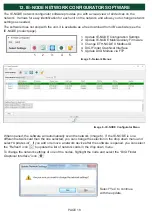
12. IE-NODE NETWORK CONFIGURATOR SOFTWARE
Page 18 - 21
13. TROUBLESHOOTING GUIDE
Page 22
14. TESTING AND MAINTENANCE
Page 22
15. WARNINGS PRESENT ON PRODUCT
Page 22
16. PRODUCT WARRANTY
Page 27
TABLE OF CONTENTS
Summary of Contents for IE-NODE 2
Page 23: ...PAGE 23 END USER NOTES...
Page 24: ...END USER NOTES PAGE 24...
Page 25: ...END USER NOTES PAGE 25...
Page 26: ...PAGE 26 END USER NOTES...


