background image


17 of 31 


Runtime Screen 


Runtime Screen 


Description: Main screen during use. The Maximum value displayed on the screen is 

99,999, or 999.9 when displaying values with decimals.


Alarm Icon (ALM) is displayed when the Alarm LED is triggered, the background also 

becomes red. Stop Icon (STP) is displayed when the Relay output is triggered. Start-

up icon (SUD) is displayed during the start-up period. Run icon (RUN) is displayed in 

place of start-up icon when the system has the Interlock connected and the start-up 

delay has elapsed (or if the interlock is not being used). 
Contents: Alarm Icon (ALM), Run Icon (RUN), Stop Icon (STP), Start-up Icon (SUD) 

Speed in digits, Units. 
Controls: Enter button – Transitions to the main menu. 

Main Menu 


Main Menu 


Description: Menus used to navigate through and select settings for the speed relay.


Contents: Scroll list, Selected Item Indicator. 
Controls: 
Up button – scrolls the current list up one. 
Down button – scrolls the current list down one. 
Enter button – activates the selected option. 


Summary of Contents for USR1V4

Page 1: ...INSTRUCTION MANUAL REV121723 Approvals Speed Relay Digital Speed Monitor Part Number USR1V4 USR1V46...

Page 2: ...siguiente c digo QR PT Para baixar a vers o digital deste manual de instru es e veri car outros idiomas dispon veis escaneie o seguinte c digo QR FR Pour t l charger la version num rique de ce manuel...

Page 3: ......

Page 4: ...USTOMER SAFETY RESPONSIBILITIES 5 PRODUCT OVERVIEW 8 PACKAGE CONTENT 8 SPECIFICATIONS 9 APPROVALS 10 DIMENSIONS 10 CONDITIONS OF USE 11 STANDARD WIRING DIAGRAM 11 INSTALLATION 15 GRAPHICAL USER INTERF...

Page 5: ...ing the proper operation and safety of the product The proper installation and maintenance of all our products is the responsibility of the user unless you have asked 4B to perform these tasks B All i...

Page 6: ...other product installation information supplied with the product You should be prepared to provide the installer with all necessary installation information to assist in the installation 4 ESTABLISH A...

Page 7: ...EST If you have questions or comments about the operation of your unit or require the unit to be serviced please call the 24 hour hotline number 309 698 5611 contact your local distributor or use one...

Page 8: ...ncy in a range of selectable units The user can set the Electromechanical Relay and PhotoMOS Solid State Relay outputs independently with their own thresholds and output behaviors and have the Alarm L...

Page 9: ...s 30 VDC 250 VAC 2 5 A MAX SSR Output Contacts 230 V AC DC 100 mA Interlock Input 18 to 28 VDC 85 to 264 VAC Indication 1x Red Alarm LED 1x Green Input LED 1x 160x80 LCD display Sensor Input Frequency...

Page 10: ...10 of 31 APPROVALS In Process DIMENSIONS ALL DIMENSIONS IN MM...

Page 11: ...es e g NEC CEC EN IEC 60079 14 and should be undertaken by an experienced and quali ed electrician All wiring must be in accordance with local and national electrical codes and should be undertaken by...

Page 12: ...P Sensor Input Input 18 to 28 VDC 4 NPN Sensor Input Output 24 VDC 50 mA 5 SSR Output A Input 230 V AC DC 100 mA 6 SSR Output B 7 Earth USR1V46 Only Input 85 to 264 VAC 50 to 60 Hz 0 03A at 230 VAC 8...

Page 13: ...ensor Wiring 2 Wire PNP Sensor Wiring 3 Wire sensors such as types E NPN E2 PNP and E3 NPN PNP Rotech Encoders 3 Wire NPN Sensor Wiring 3 Wire PNP Sensor Wiring 4 Wire sensors such as P1003V34AI P3003...

Page 14: ...supply from pin 1 to power a sensor which is rated for 100 mA A 2 wire NPN sensor can be powered from Terminal 4 which is rated for 24 VDC 50 mA If the Speed Relay is powered via DC using terminals 1...

Page 15: ...o NOT USED the state of the interlock does not matter INSTALLATION The Speed Relay should be wired as show in the connection diagrams in Electrical Setup Speed Relay Mounted on 35mm DIN rail The Speed...

Page 16: ...th Screwdriver GRAPHICAL USER INTERFACE Splash Screen Splash Screen Description Initial screen displayed for 4 seconds on start up before transitioning to the runtime screen Contents Device Name 4B Lo...

Page 17: ...n RUN is displayed in place of start up icon when the system has the Interlock connected and the start up delay has elapsed or if the interlock is not being used Contents Alarm Icon ALM Run Icon RUN S...

Page 18: ...Save Profile Screen 11 Load Profile Transitions to the Load Profile Screen 12 Test Outputs Transitions to the Test Screen 13 Manual QR code Transitions to the QR code screen 14 Factory Reset Transiti...

Page 19: ...selected digit indicator calibration point value PPM Controls Up button increases the selected digit by 1 to a maximum PPM of 60000 Down button decreases the selected digit by 1 to a minimum PPM of 0...

Page 20: ...SSR Output Range The SSR Output triggers outside the selected range Relay Follow SSR Output uses the settings for the relay output Pulse SSR Output pulses at the measured input frequency Alarm LED Re...

Page 21: ...increases the selected digit by 1 to a maximum PPM of 60000 or unit equivalent Down button decreases the selected digit by 1 to a minimum PPM of 0 or unit equivalent Enter button selects the next digi...

Page 22: ...u Factory Reset Screen System Reset Screen Description The factory reset screen allows the user to wipe all user settings from the Speed Relay All saved settings will return to the default values Cont...

Page 23: ...creen this will load the selected pro le and return to the system menu And on the save screen this will save the current settings into the selected pro le slot and transition to the system menu Test S...

Page 24: ...24 of 31 Manual Screen Manual Screen Description The Manual screen displays a QR code that links to the URL of the product manual Contents QR code Controls Enter button Transition to the System menu...

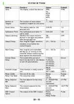
Page 25: ...y How long the unit waits after starting up or turning on the Interlock before measuring the input against the thresholds 0 0 100 0 s 5 0 s Screen Sleep Delay The length of the period of inactivity re...

Page 26: ...setpoint for the SSR Output 0 60000 PPM or unit equivalent 0 PPM SSR Output Setpoint Max The second setpoint for the SSR Output 0 60000 PPM or unit equivalent 0 PPM Alarm LED Option The output of the...

Page 27: ...o the correct input terminal of the unit e g NPN sensor wired to the NPN input terminal 4 Make sure sensor is outputting pulses correctly 0 PPM is displayed even though Input LED is ashing 1 Make sure...

Page 28: ...ical connections are secure and in good order 3 Test that the Speed Relay receives input pulses with the Input LED ashing and a speed calculated on the display 4 Test that the outputs trigger using th...

Page 29: ...29 of 31 NOTES...

Page 30: ...t are due to product misuse abuse or misapplications as authorized by law 4B speci cally disclaims all warranties that the product is t or merchantable for a particular purpose 3 NO WARRANTY BY SAMPLE...

Page 31: ...iland 4B Asia Paci c Build No 899 1 Moo 20 Soi Chongsiri Bangplee Tam Ru Road Tanbon Bangpleeyai Amphur Bangplee Samutprakarn 10540 Tel 66 0 2 173 4339 France 4B France 35 bis rue du 8 mai 1945 Viller...

Reviews: