


24
6022221B - Direct Drive HVLS Fan UM
November 2022
Installation
INSTALLATION
Before installation, make certain that the
power is disconnected and properly locked
out.
For fans that will be subjected to high cross
winds due to open bay doors or air conditioning
diffuser ducts, the fan must be at least one fan
diameter (as measured from the end of the
winglet) from open bays or A/C ducts mounted
below the blade plane or there must be at least
two fan diameters (as measured from the end of
the winglet) for A/C ducts mounted at or above
the blade plane.
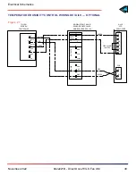
INSTALL FAN MOUNT
1.
Fasten the pivot brackets to the extension
tube with ears outboard.
2.
Leave the 1/2” dia. x 4-1/2” bolts and nylock
nuts finger tight. See
Figure 6
.
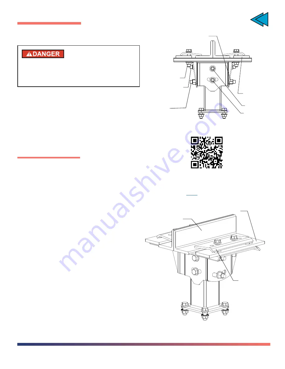
STANDARD I-BEAM
1. Locate the fan mount assembly on the
bottom of the building support beam.
2. Align the mount assembly so that it is
centered and square to the beam.
3. Orient the mount such that the pivoting axis
is aligned with the building slope, if required.
4. Install the clamps.
5.
Add shims as required for thick flange
I-Beams.
Figure 6
Pivot bolt
Shim (x2)
(as req’d)
1/2-13UNC x 2-1/2 bolts (x4)
1/2-13UNC
lock nut (x4)
Angle
adjustment
bolt
Pivot bolt
Angle
adjustment
bolt
Mounting Options
to view the video
Figure 7
Building structure
Clamp plate
Shim
TOC


