


32
6022221B - Direct Drive HVLS Fan UM
November 2022
Installation
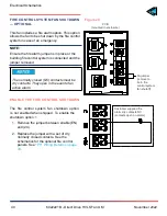
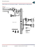
INSTALL THE REMOTE CONTROL
Do not over-torque the mounting screws.
Damage to the display screen may occur if
you over-torque the mounting screws.
It is your responsibility to torque the screws
properly..
1. Mount the touchscreen remote 53” above
the floor to the factory supplied junction box
inside the building.
Mount the touch screen as close to the fan
assembly as practical. See
Figure 21.
NOTE:
For remote signal (blue) CAT5e cable runs
exceeding 1000’, consult the factory.
Blue CAT5e cable has terminated ferrules
at the remote end. PROTECT these ferrules
during cable routing.
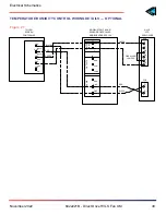
2. Route the remote signal (blue) cable
(6015651) from the top of the VFD box
through the hole in the factory supplied
junction box.
3. Wire the four leads of the remote signal
cable (blue) to the orange connector of the
touch screen remote control.
4. Neatly coil any excess blue cable length
and secure it near the VFD box.
5. Mount the touch screen to the junction box
using the provided fasteners.
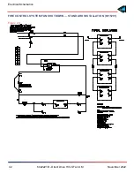
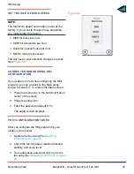
Install Remote Control
Click
Figure 21
Touch screen
1/2 NPT port
Junction box
Touch screen
(back view)
Remote signal
(blue) cable
Blue label
bulkhead
connector
Power from
building
source
S.O. cable
from fan
VFD box
(top view)
Voltage
label
WHT/BRN
BRN
WHT/GRN
GRN
See Fig. 47
4' 5" from center to ground.
TOC


