November 2022
6022221B - Direct Drive HVLS Fan UM
33
Electrical Schematics
ELECTRICAL SCHEMATICS
Before doing any electrical work, make certain the power is disconnected and properly locked
out and tagged out.
Failure to do so may result in death or serious injury.
All electrical troubleshooting and repair must be done by a qualified technician and meet all
applicable codes.
Do not route control wiring for any other device through this control box. Ensure the voltage and
phase of the incoming power agrees with the label on the top of the VFD box and fan.
Be certain the power is off when wiring to the control box. Failure to do so may result in electrical
shock, death, or serious injury.
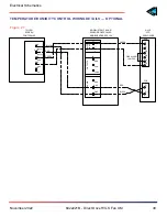
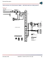
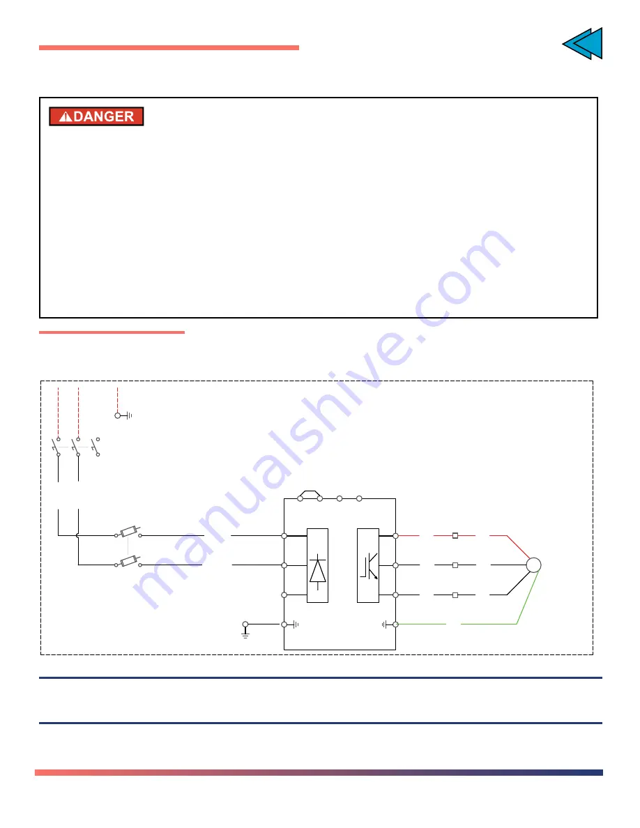
1PH WIRING DETAILS
Figure 22
2
1
FU116
600V/16A
DISCONNECT
DS103
1
2
3
4
5
6
MOT107
SEE CHART
1750RPM
HP
.
.
BLK 12AWG
RED
.
.
BLK
.
.
.
.
WHT 12AWG
WHT
.
.
1061
1071
4
1071
3
RED
.
.
WHT
.
.
GRN
.
.
R/L1
S/L2
T/L3
P1
P/+
PR
N/-
U
V
W
JUMPER
VARIABLE SPEED
FAN CONTROL
SEE CHART FOR RATINGS
POWER CIRCUIT
VFD
BLK
.
.
BLK 12AWG
.
.
WHT 12 AWG
.
.
SINGLE PHASE WIRING
1063
1073
1083
NOTE 1
NOTE 2
1031
1032
U
TS1
V
TS1
W
TS1
L1
L2/N
NOTE:
Terminals will accept stranded wire only
TOC


