©2014 4Front
®
Engineered Solutions, Inc.
May 2014
6015653B — HVLS Fans
13
inStaLLation,
continued
inStaLL Motor coVer
1. Ensure that the motor SO cable has been routed to VFD
box and is secured. See electrical installation instructions.
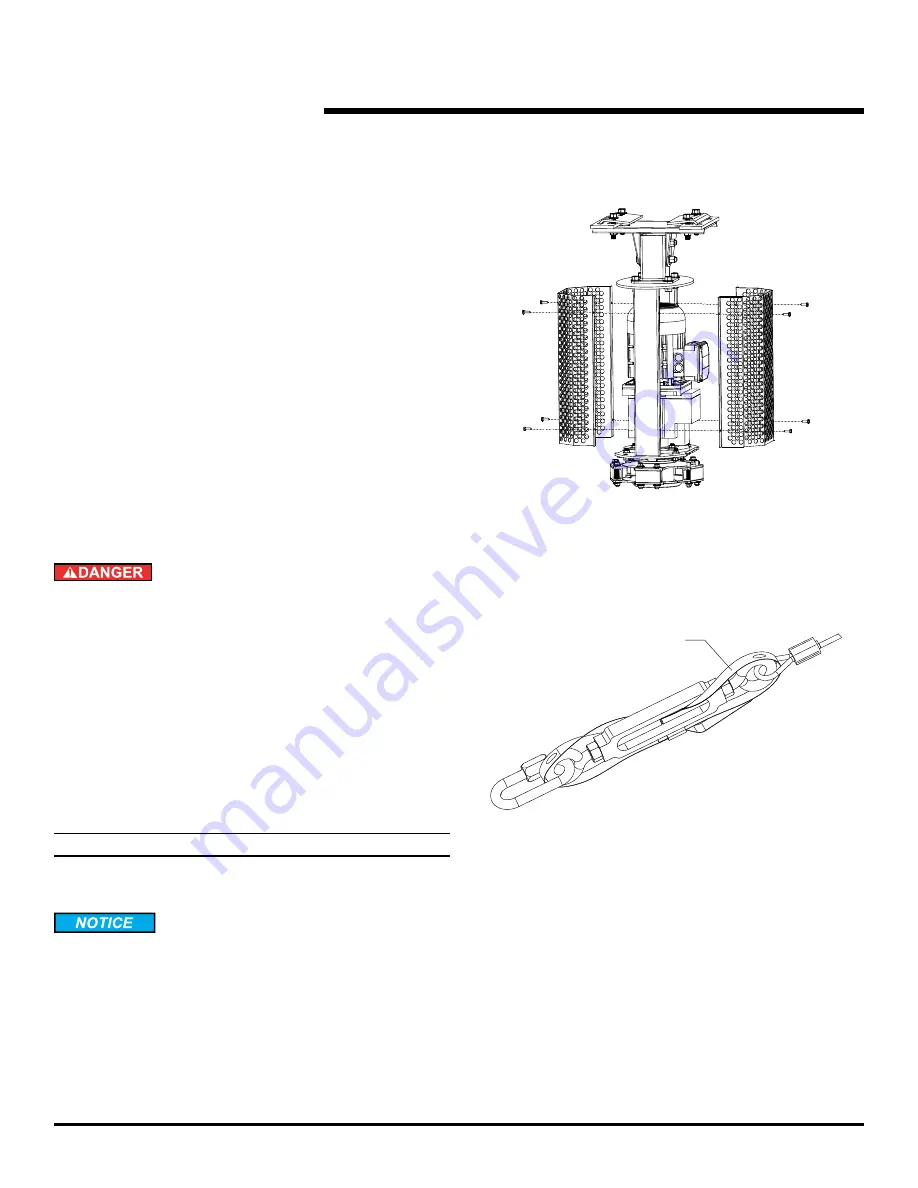
2. Locate each motor cover and install the cover fasteners.
Do not overtighten. See Fig. 15.
VeriFy cLearance and cabLe tenSion
1. Rotate fan by hand and observe clearance of each blade
with closest obstruction. If necessary, reposition fan.
Blade tips droop when not in operation and rise when in
operation. Reference chart on page 7 for min. clearance.
2. Verify guy wire tension by attempting to move powerhead
in any horizontal direction. If movement is detected, re-
tension guy wires.
3. Lock the individual turnbuckles using the stop nut on each
and secure it with the turnbuckle strap. See Fig. 16.
eLectricaL inStaLLation
Before doing any electrical work, make certain the power
is disconnected and properly locked or tagged off. Failure
to do so may result in death or serious injury. All electrical
troubleshooting and repair must be done by a qualified
technician and meet all applicable codes. Do not route
control wiring for any other device through the control
box. Ensure that the voltage and phase of the incoming
power agrees with the label located on top of the VFD
box and fan. Be certain power is off when wiring to the
control box. Failure to do so could result in electrical
shock, death or serious injury.
Standard UnitS
note:
Reference wiring diagrams on pages 26-30 for all field
connections.
Do not over-torque mounting screws. Damage to display
screen may occur if mounting screws are over-torqued.
It is the installer’s responsibility to torque properly.
Fig. 15
Fig. 16
Turbuckle strap


