105
User Manual ENGLISH
WHG-Series Wireless WLAN Controller
Copyright © 2017, 4ipnet, Inc. All rights reserved. All other trademarks mentioned are the property of their respective owners.
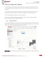
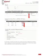
Floor Plan Name: Self-defined name for Administrator’s reference.
Floor Plan: Select file for floor plan (.jpg format).
Wall: Select file for wall (.xml format).
Map Width: Actual width of floor plan.
Map Length: Actual length of floor plan.
Country Code: Select the country code (EU/US). This will determine the max output power of access
points
Height of Receiving Device (m): The assumed average height of receiving client devices.
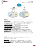
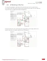
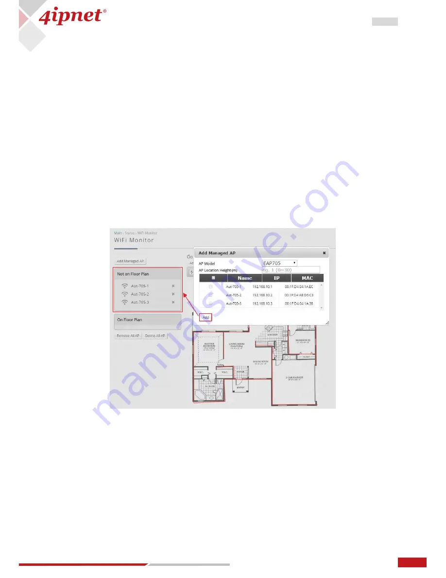
Managed AP Simulation is a used for monitoring of Access Points based on location. The APs on the
Managed AP Simulation floor plan are real managed Access Points on the Controller (either by Local AP
Management or Wide AP Management).
Access Points here are linked to APs managed by the WLAN controller, and we can see real AP information
such as the IP address, MAC address, and Associated Client number. This allows the administrator to easily
visualize the wireless network with respect to the APs’ location.
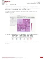
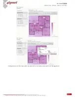
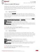
Once these managed APs are created, simply drag and drop these APs onto the floor plan. 2.4GHz is
indicated blue and 5GHz is indicated red for signal strength (hence purple when both bands are
overlapping).
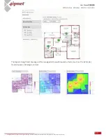
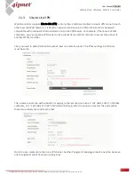
Signal Strength: The darker the color, the stronger the signal strength is.
Coverage: Different colors depict the different coverage area of each AP.
Distribution: Use different colors to illustrate the strength of signals.

