35
User Manual ENGLISH
WHG-Series Wireless WLAN Controller
Copyright © 2017, 4ipnet, Inc. All rights reserved. All other trademarks mentioned are the property of their respective owners.
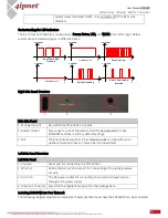
Understanding the LED indicators
There are four LED indicators on the panel : Power, Status, LAN, and WLAN from left to right. Below
summarizes all indication types in different states:
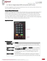
Right Side Panel Overview
Left Side Panel Overview
Including SDS200W into Your Network
The following diagram illustrates a deployment example that shows how the SDS200W can be connected
t
Amplitude
long illuminated
intervals
Amplitude
Fast Flashing
t
Amplitude
Constantly on
Amplitude
Constantly off
t
Amplitude
Special flashing
t
t
Amplitude
Short illuminated
intervals
t
system detects wireless traffic. It is constantly off if the RF card is
disabled.
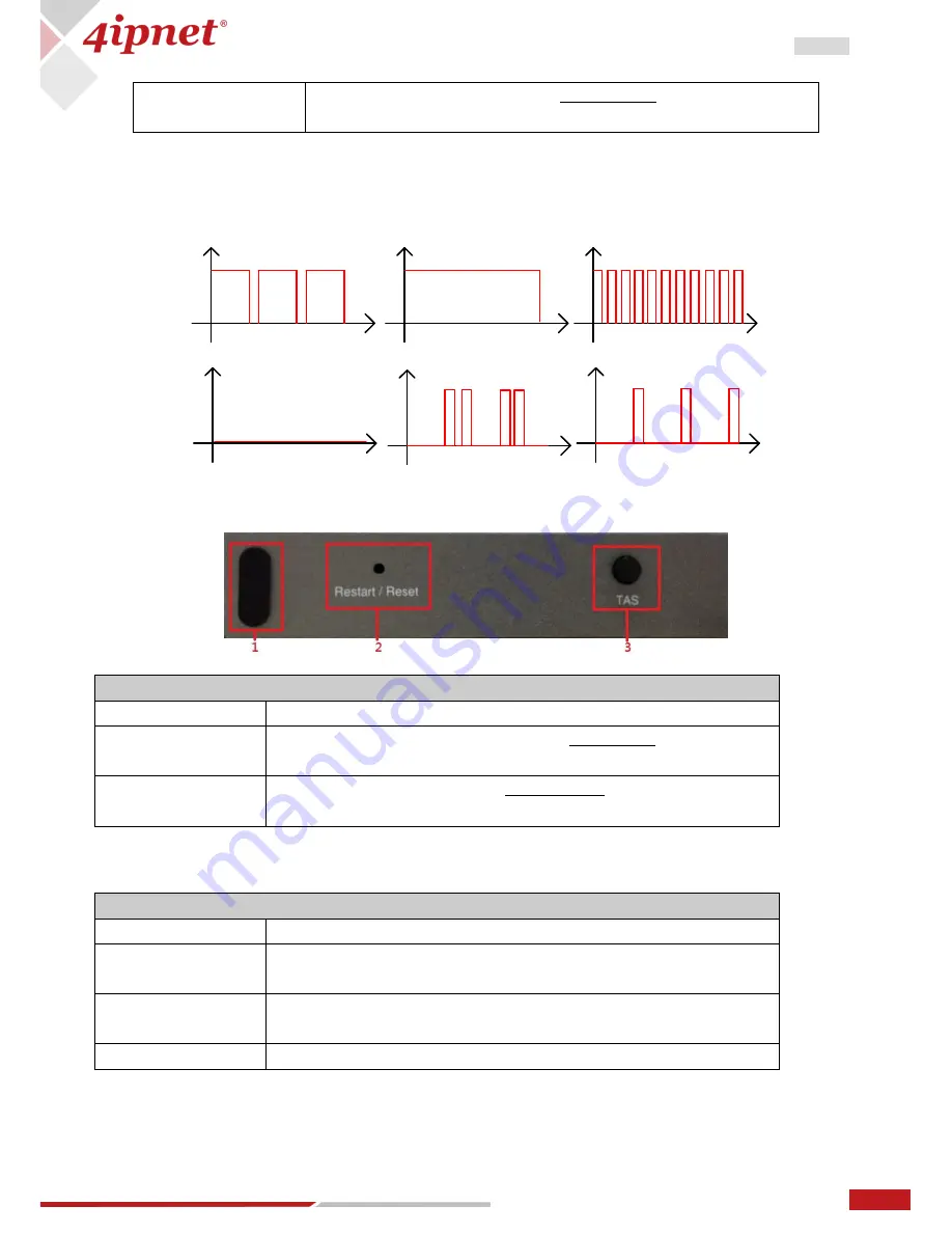
Ride Side Panel
1. Kensington Lock
Be used to lock the device to a pole.
2. Restart / Reset
Press once to reboot the system. Hold for five seconds to make
SDS200W set back to factory default settings.
3. TAS
Terminal Auto Setup (TAS). Press three seconds to initiate the auto
uplink connection process. This will be introduced later.
Left Side Panel
1. Console
Serial port for connecting to a POS printer.
2. Ethernet
RJ-45 Ethernet port Serial port for connecting to the uplink gateway
via wire.
3. 5V / 1.5A
The DC power socket for connecting to an external power source
through a DC power supply.
4. Antenna Connector Assemble the dipole antenna within the package here.

