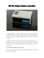


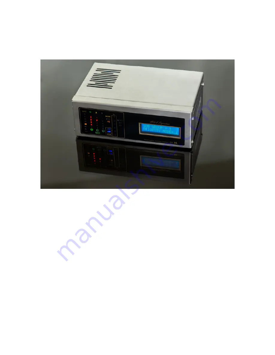
SSC-XL Deluxe Station Controller
Congratulations on your purchase of the SSC-XL Deluxe Station Controller from
4O3A. The SSC-XL is the most complete, easy-to-use, amateur radio station
controller available. It is designed for high performance, with future expansion
capability.
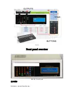
The SSC-XL can work as a stand-alone controller. It is programmable by a PC
application. You can control it with an optional external keyboard, or it may be
connected to a PC via a USB cable for desktop control of virtually any device in
your station.
We hope that you will enjoy your new SSC-XL!
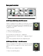
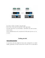
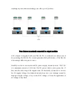
SSC XL is a very flexible platform with an almost infinite number of possible
uses / interconnections:


