background image


26


Figure 35 – Creating a Marker Set 


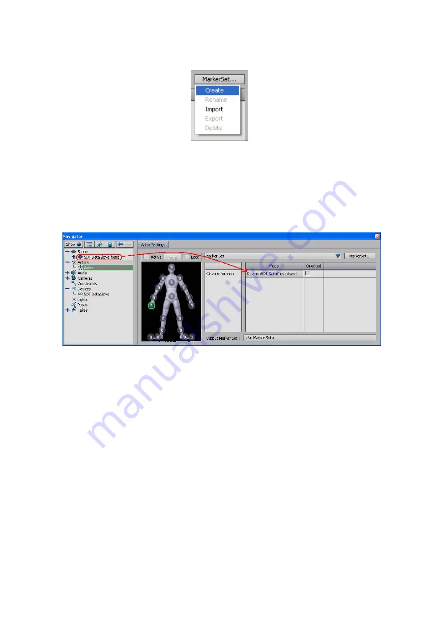
Once a Marker Set has been selected, select the hand marker to which the 
glove should be referenced. Drop the root of the glove device (under the Scene 
branch) into the Glove Reference in the Model column. Click on the Active 
checkbox to make the actor active (real-time animations are shown). 


Figure 36 – Assigning a Glove Reference to a Marker Set 


Summary of Contents for Data Glove Ultra Series

Page 1: ...5DT Data Glove Ultra Series User s Manual Fifth Dimension Technologies www 5DT com ...

Page 2: ...o part of this manual software or hardware may be copied reproduced translated or reduced to any electronic medium or machine readable format without the written consent of 5DT Fifth Dimension Technologies All trademarks and trade names are the respective property of their owners Version 1 2 January 2007 ...

Page 3: ...ial and Wireless Gloves 8 4 3 1 Scanning for Gloves 8 4 3 2 Opening Gloves 8 4 4 The Graph View 10 4 4 1 The Menu Bar 11 4 4 2 Toolbar 12 4 4 3 Tab Bar 13 4 4 4 The Sensor Graphs 13 4 4 5 The Sensor Info Box 14 4 4 6 The Status Bar 16 4 5 The Sensor Selection View 16 4 6 Glove Calibration 17 4 7 Recording 19 5 Using the Gloves in Kaydara MOCAP 20 5 1 Installation 20 5 2 Opening the Glove 20 5 3 Op...

Page 4: ...1 General Troubleshooting 33 7 1 1 Physical Connection Problems 33 7 1 2 Software Connection Problems 33 7 2 Frequently Asked Questions FAQ 33 7 3 Support 34 8 Warranty Information 35 8 1 Thirty 30 Day Customer Satisfaction Guarantee 35 8 2 One 1 Year Product Warranty 35 8 3 Exclusions 35 8 4 Warranty Claim Instructions 35 9 About 5DT 37 Appendix A Hardware Specifications 39 Appendix B Serial Prot...

Page 5: ...o places 1st joint knuckle 2nd joint on each finger Among the features of this kit are The glove is comfortable with an improved design for differently sized hands The accurate and sensitive sensors give a clean signal minimizing the need for additional filtering Diagnostic software is included with the capability to record hand data The package includes a plug in for Kaydara MOCAP The gloves func...

Page 6: ... immediately The 5DT Data Glove Ultra consists of the following 1 5DT Data Glove Ultra 5 or 14 Sensor 2 5DT Data Glove Ultra Series USB cable 3 5DT Data Glove CD 2 2 Connecting the Glove Connect the glove to the PC as shown in Figure 1 Figure 1 Connecting the Glove to the PC You can use GloveManager to test the operation of the glove Detail on this is given in Section 4 of this manual ...

Page 7: ... directory and follow the on screen instructions When prompted check the 5DT Data Glove Ultra box to install the software for this product 3 1 CD Contents The CD contains the following directories Acrobat This copy of Adobe Acrobat Reader will allow you to read the documentation DirectX The CD ROM also contains the redistributable version of DirectX 9 0 You will need this if you want to run the Di...

Page 8: ...at and application notes as they become available GloveManager GloveManager is a program that allows you to test your gloves and access advanced glove functions which may not be available in the plug ins More detail on this is given in Section 4 Plugins This directory contains the plug in for Kaydara MOCAP which replaces the built in Kaydara glove plug in More detail on this is given in Section 5 ...

Page 9: ...e Data Glove 14 Ultra Images will differ slightly for the Data Glove 5 Ultra 4 1 Starting GloveManager Start the program by running GloveManager exe which is installed in the Data Glove Ultra GloveManager folder by default The setup tab window will appear see below Figure 2 The Setup Tab Window 4 2 Opening USB Gloves 4 2 1 Scanning for Gloves Clicking the button in the setup tab window causes Glov...

Page 10: ... into Port A of the wireless transmitter unit The left hand glove is plugged into Port B 4 2 2 Opening Gloves A glove may by opened by clicking the button after a USB glove has been selected in the device tree Figure 4 Selecting the Glove to be Opened If the glove has been successfully opened the tab window will automatically switch to the newly opened glove as shown in Figure 5 Double clicking on...

Page 11: ...e 5 GloveManager after the USB Glove is Successfully Opened Clicking on the tab will cause GloveManager to display the setup tab window again To open the second wireless glove select it from the COM port tree ...

Page 12: ...the Port Scan As can be seen in Figure 6 the Port Scan has found two wireless gloves on COM1 The right hand glove is plugged into Port A of the wireless transmitter unit The left hand glove is plugged into Port B 4 3 2 Opening Gloves A glove may by opened by clicking the button after a COM port has been selected in the COM port tree Figure 7 Selecting the First Glove to be Opened If the glove has ...

Page 13: ...Manager to display the setup tab window again To open the second wireless glove select it from the COM port tree Figure 9 Selecting the Second Glove to be Opened Click on the button again to open the second glove If GloveManager was successful in opening the second glove a new glove tab window will appear ...

Page 14: ...95 o Sensor dynamic range Value between 0 and 4095 o Scaled sensor value Scaled value from 0 to 4095 o Lower calibrated value Value between 0 and 4095 o Upper calibrated value Value between 0 and 4095 o Graph top value Value between 0 and 4095 o Current graph value Value between 0 and 4095 o Graph bottom value Value between 0 and 4095 Status bar Displays status information such as o Program status...

Page 15: ...ent recording File Save Recording As Saves the current recording as a new file name File Close Current Glove Alt C Closes the currently visible glove File Exit Exits GloveManager View Toolbar Shows Hides the Toolbar View Status Bar Shows Hides the Status Bar View Show View Setup V Toggles between the sensor selection and the graph view View Show Scaled Graphs S Shows Hides the Scaled Graphs View S...

Page 16: ...Menu Commands Available in GloveManager 4 4 2 Toolbar The following buttons are available on the toolbar Icon Shortcut Description Ctrl N Creates a new recording file Ctrl S Saves the current recording Ctrl R Toggles recording of glove data on or off X Shows Hides the raw graphs S Shows Hides the scaled graphs R Resets the auto calibration values and turns auto calibration on Alt O Load the calibr...

Page 17: ...tween 0 and 4095 The raw graph showing the raw values between 0 and 4095 4 4 4 1 Scaled Graph The scaled graph shows the scaled version of the sensor value normalized between 0 and 1 The default color for this graph is blue Figure 13 The Scaled Graph 4 4 4 2 Raw Graph The raw graph represents the raw sensor value coming from the glove Additional to the actual graph of the raw values drawn in red b...

Page 18: ...ion value 4 4 5 The Sensor Info Box The sensor info box provides the following information see Figure 16 Raw sensor value Value between 0 and 4095 Sensor dynamic range Value between 0 and 4095 Scaled sensor value Scaled value from 0 to 4095 Lower calibrated value Value between 0 and 4095 Upper calibrated value Value between 0 and 4095 Graph top value Value between 0 and 4095 Current graph value Va...

Page 19: ...ual calibration during fine tuning The sensor info box has three levels of detail depending on the pixel resolution available to GloveManager The highest level of detail is shown in Figure 16 As the pixel resolution decreases the second level of detail is switched to as in Figure 17 The value shown next to the sensor name is the current scaled value when scaled graphs are visible the current raw v...

Page 20: ... calibration indicator Figure 19 The Status Bar 4 5 The Sensor Selection View The sensor selection view may be obtained by clicking the button on the toolbar by selecting the View Show View Setup option from the menu or by pressing the V shortcut key The view is shown in Figure 20 The hand and sensor image on the left allows you to select sensors to be used during recording Selecting none means th...

Page 21: ...om the menu or by pressing the V shortcut key 4 6 Glove Calibration Figure 20 The Sensor Selection View Glove calibration values may be loaded from file by clicking the button by selecting the Calibration Load Calibration Values menu option or by using the Alt O shortcut key The file open dialog box will appear ...

Page 22: ...ration file extension cal and click on the button to open the file Glove calibration values may be saved to file by clicking the button by selecting the Calibration Save Calibration Values menu option or by using the Alt S shortcut key The file save dialog box will appear ...

Page 23: ...on or by using the Ctrl R shortcut key This will cause GloveManager to record the latest raw and scaled values at a fixed rate of 60 Hz Only the sensors selected for recording in the sensor setup view see section 4 5 will be recorded These values are recorded in memory and will be lost unless saved to file The values may be saved to file by clicking the button by selecting the File Save or File Sa...

Page 24: ...in the Windows System folder 3 Run MOCAP 4 Verify that the driver is installed by clicking on the Devices tab in the asset browser The installed driver should be visible as shown in the red rectangle as shown in Figure 23 below Figure 23 Verifying that the 5DT Data Glove Plugin has been Installed 5 2 Opening the Glove From the device pane of the Asset Browser create a glove in Kaydara by clicking ...

Page 25: ...n scan the USB and all COM ports for available gloves and update the Ports drop down list The progress of the scan process is shown in the status bar in the Viewer window Please note that the scan process may take a while Once the correct port has been selected click on the Online button If the red button turns green a successful connection has been made 5 3 Opening Wireless Gloves The new 5DT Dat...

Page 26: ...he viewer window and a port scan is performed We can see that there is a glove present on COM1 A Figure 26 Result of the First Port Scan 2 The first glove is opened by selecting the correct port and clicking on the Online check box Figure 27 Glove A has been opened 3 The second glove is created by dragging the 5DT DataGlove icon from the device pane into the viewer window The driver automatically ...

Page 27: ... on the Auto Calib button The button text will change to Click to Stop Once you are satisfied with the calibration values click the button again to stop calibrating The following calibration process is recommended 1 Hold your hand in a relaxed open position and click on the Relax Open button 2 Open all of your fingers as wide as possible and click on the Wide Open button 3 Close all of your finger...

Page 28: ...been issued the wire frame hand model is created in the viewer and the model s name is added to the Model binding drop down list Figure 31 The Model Binding Drop down List with Hand Figure 32 The Glove Model as Shown in the Viewer Window This glove can now be automatically connected to an actor To create an actor click and drag the Actor icon from the Characters pane in the Asset Browser ...

Page 29: ...et is selected in the Navigator window the Actor Settings window will appear Figure 34 The Actor Settings Window If no Marker Set exists for this actor create one by clicking on the MarkerSet button A popup menu will appear Select the Create option ...

Page 30: ... marker to which the glove should be referenced Drop the root of the glove device under the Scene branch into the Glove Reference in the Model column Click on the Active checkbox to make the actor active real time animations are shown Figure 36 Assigning a Glove Reference to a Marker Set ...

Page 31: ... Using the SDK The 5DT Data Glove Driver is easy to implement using the following guidelines 1 Make sure that the header file fglove h the library file fglove lib and the dynamic link library file fglove dll reside in the current application directory or somewhere that they can be found The file fglove dll may be copied into your Windows system directory 2 Include the header file fglove h in the a...

Page 32: ... 5 Sensor Mappings for the 5DT Data Glove 5 The sensors on the 5DT Data Glove 5 are positioned as in Figure 37 Figure 37 Sensor Positions for the 5DT Data Glove 5 Sensor Driver Sensor Index Description A 0 1 Thumb flexure B 3 4 Index finger flexure C 6 7 Middle finger flexure D 9 10 Ring finger flexure E 12 13 Little finger flexure F 16 Pitch angle of tilt sensor G 17 Roll angle of tilt sensor Tab...

Page 33: ... second joint 2 2 Thumb index finger abduction 3 3 Index finger flexure at knuckle 4 4 Index finger flexure second joint 5 5 Index middle finger abduction 6 6 Middle finger flexure at knuckle 7 7 Middle finger flexure second joint 8 8 Middle ring finger abduction 9 9 Ring finger flexure at knuckle 10 10 Ring finger flexure second joint 11 11 Ring little finger abduction 12 12 Little finger flexure...

Page 34: ...n to obtain a closed gesture and the minimum to obtain an open gesture Closed gestures take precedence in other words bending only one joint of a finger will count as a closed gesture Finger Little Ring Middle Index 5DT Data Glove 5 sensor E D C B 5DT Data Glove 16 14 Ultra sensor 12 13 9 10 6 7 3 4 Driver sensor index 12 13 9 10 6 7 3 4 Gesture Number Flexure 0 flexed 1 unflexed Gesture Descripti...

Page 35: ...int 8 Little finger point 9 Index and little finger point 10 Little middle finger point 11 Not ring finger point 12 Little ring finger point 13 Not middle finger point 14 Not index finger point 15 Flat hand Figure 16 Gesture Illustrations When the 5DT Data Glove 16 or 5DT Data Glove 14 Ultra is used the driver sensor indices will return different values The maximum of the two values will ...

Page 36: ...rwritten The upper and lower calibration values are therefore continuously pushed outwards The normalized output is given by the first order equation min max min Max raw raw raw raw out val F 1 which is in 0 Max The value of Max is set by the functions fdSetSensorMaxAll and fdSetSensorMax Doing a few flexing movements with the hand quickly sets the operating values for rawmin and rawmax and calibr...

Page 37: ...r device for example an external modem If the 5DT Data Glove is recognized by your computer but not connecting properly proceed directly to the software connection problems section 7 1 2 Software Connection Problems Run GloveManager from the start menu Check which COM ports are available by looking at the list in Figure 3 Remember that not all available ports will be physically connected to a sock...

Page 38: ...e of the fibers has failed The glove will then have to be returned to the supplier or 5DT for repairs 7 3 Support If you experience problems or have complaints suggestions or other comments please feel free to contact your supplier preferably via e mail Please have the following information available or include it in your written correspondence 1 Computer processor make and model e g Pentium IV 3 ...

Page 39: ...of the product including but not limited to Location based entertainment LBE applications Trade show demonstrations This warranty shall not apply to defects resulting from the following Misuse Improper or inadequate maintenance Unauthorized modification 8 4 Warranty Claim Instructions Please use the following procedure if you require warranty service 1 Contact your supplier to determine if you nee...

Page 40: ... prepaid to your supplier or to 5DT 7 When completing customs or courier documentation please clearly indicate Unit returned for repairs under warranty 5DT is not responsible for any damage that may occur during shipping Shipping charges to 5DT are your responsibility COD shipments will not be accepted by 5DT ...

Page 41: ...noculars 5DT Head Mounted Display HMD 5DT Virtual Binoculars 5DT Motion Base VR Software Systems developed by 5DT include Automotive o Driving Training Simulator Series o Road Safety Training System Aviation o Airspace Visualizer o Air Traffic Control ATC Training Simulator o Experimental Avionics Testbed o Unmanned Aerial Vehicle UAV Training Simulator Defense o Air Defense Training Simulator o F...

Page 42: ...Dragline Training Simulator Visualization o Flight Visualization System o Flow Visualization System o High Voltage Line Visualization System Other o Virtual Landscape Generation Technology Contact Information United States and Americas 5DT Inc 15375 Barranca Pkwy G 103 Irvine CA 92618 USA United States of America Tel 1 949 450 9044 Fax 1 949 450 9045 e mail info us 5dt com Web www 5dt com Rest of ...

Page 43: ... Proprietary fiber optic based flexor technology 1 sensor per finger measures average of knuckle and first joint COMPUTER INTERFACE Full speed USB or RS 232 3 wire GND TX RX 115kbps 8 data bits 1 stop bit no parity POWER SUPPLY Maximum 5 V DC Center positive DC power connector SAMPLING RATE The full hand all available sensors may be sampled at least 60 times per second At 5DT we constantly try to ...

Page 44: ...then the other It is possible to distinguish the two by identifying the glove type from the type byte The data packet sent by the glove is structured as follows Byte No Byte Byte No Byte 1 Start 17 9Ll 10Hl 2 Type Byte 18 10Lu 10Ll 3 Version 19 11Hl 11Lu 4 1Hl 1Lh 20 11Ll 12Hl 5 1Ll 2Hl 21 12Lu 12Ll 6 2Lu 2Ll 22 13Hl 13Lu 7 3Hl 3Lu 23 13Ll 14Hl 8 3Ll 4Hl 24 14Lu 14Ll 9 4Lu 4Ll 25 15Hl 15Lu 10 5Hl ...

Page 45: ...a Glove 5 Ultra wireless left hand glove Port A 0x16 Data Glove 5 Ultra wireless right hand glove Port B 0x17 Data Glove 5 Ultra wireless left hand glove Port B Version The firmware version byte The upper nibble Vmaj represents the version major the lower nibble Vmin represents the version minor xHl The upper four bits of the 12 bit sensor value or the lower nibble of the MSB of the 12 bit sensor ...

Page 46: ...nt fdClose fdGlove pFG Frees the glove device and communications port Return value Returns nonzero if successful zero if an error occurred Parameters pFG Pointer to a glove device This is the value returned by fdOpen Remarks It is important to call this function when you are finished using the glove int fdScanUSB unsigend short aPID int nNumMax Scans the USB for available gloves Return value Retur...

Page 47: ...e enumerated type EfdGloveTypes Parameters pFG Pointer to a glove device This is the value returned by fdOpen Remarks FD_GLOVE7 and FD_GLOVE7W refer to the original 5 2 tilt angles sensor glove 5DT Data Glove 5 The W suffix indicates a wireless model FD_GLOVE16 and FD_GLOVE16W refer to the Data Glove 16 FD_GLOVE14 FD_GLOVE14W and FD_GLOVE14_USB refer to the Data Glove 14 Ultra The USB suffix refer...

Page 48: ... will contain the raw sensor values The size of the array must always match the value returned by fdGetNumSensors Remarks Currently the raw sensor samples are all 12 bit unsigned values The range is therefore from 0 to 4095 Note that this is not the dynamic range of the sensors There can be severe offset values associated with each sensor The enumerated type EfdSensors defines the finger mapping f...

Page 49: ...t can be mapped will be overwritten rendering the forced value void void fdSetSensorRaw fdGlove pFG int nSensor unsigned short nRaw Forces the raw value for a specific sensor Return value None Parameters pFG Pointer to a glove device This is the value returned by fdOpen nSensor Index of the sensor that is being set The value must lie in the range given by the enumerated type EfdSensors or alternat...

Page 50: ...ch sensor float fdGetSensorScaled fdGlove pFG int nSensor Obtains the most recent scaled auto calibrated value for a specific sensor from the currently connected glove Return value Returns a floating point sensor value Parameters pFG Pointer to a glove device This is the value returned by fdOpen nSensor Index of the sensor that is being set The value must lie in the range given by the enumerated t...

Page 51: ... void fdGetCalibrationAll fdGlove pFG unsigned short pUpper unsigned short pLower Obtains the current auto calibration settings of the driver Return value None Parameters pFG Pointer to a glove device This is the value returned by fdOpen pUpper and pLower Arrays of 16 bit unsigned integers that will contain the maximum and minimum raw sensor values The size of each array must always match the valu...

Page 52: ...pper and pLower Arrays of 16 bit unsigned integers containing the maximum and minimum raw sensor values The size of each array must always match the value returned by fdGetNumSensors Refer to section 6 for details Remarks For unmapped sensors it would be sensible to set the upper and lower calibration settings above and below the raw value forced with fdSetSensorRaw and fdSetSensorRawAll void fdSe...

Page 53: ...the application starts up or the glove changes users during run time For unmapped sensors the upper and lower calibration values are set to 4095 and 0 respectively which is the inverse of the auto calibration settings If auto calibration was turned off it is turned on again void fdResetCalibration fdGlove pFG int nSensor Resets the internal auto calibration settings of the driver to appropriate de...

Page 54: ...value of 1 for each sensor float fdGetSensorMax fdGlove pFG int nSensor Obtains the maximum scaled value for a specific sensor Return value Returns the maximum scaled values of the sensor Parameters pFG Pointer to a glove device This is the value returned by fdOpen nSensor Index of the sensor that is being queried The value must lie in the range given by the enumerated type EfdSensors or alternati...

Page 55: ...by fdGetNumSensors minus one fMax A floating point value that contains the maximum scaled sensor value Remarks The glove driver defaults to a maximum scaled value of 1 for each sensor void fdGetThresholdAll fdGlove pFG float pUpper float pLower Obtains the current gesture recognition threshold settings of the driver Return value None Parameters pFG Pointer to a glove device This is the value retur...

Page 56: ...FG float pUpper float pLower Sets the current gesture recognition threshold settings of the driver Return value None Parameters pFG Pointer to a glove device This is the value returned by fdOpen pUpper and pLower Arrays of floating point numbers that contains the maximum and minimum threshold values The size of each array must always match the value returned by fdGetNumSensors Refer to section 6 f...

Page 57: ...y fdOpen pData Array of 32 bytes that will contain the information data Remarks The information data is specified in the glove user s manual The size of the information block is always 32 bytes void fdGetDriverInfo fdGlove pFG unsigned char pData Obtains the information data block of the driver Return value None Parameters pFG Pointer to a glove device This is the value returned by fdOpen pData Ar...

Page 58: ...None bool fdNewData fdGlove pFG Indicates if the driver has received new data since this function was last called Return value Returns true if new data is available Parameters pFG Pointer to a glove device This is the value returned by fdOpen Remarks This function may be used as an alternative to using the callback function to trigger events upon the arrival of new glove data bool fdNewData fdGlov...

Page 59: ... minor version of the glove s firmware as an integer Parameters pFG Pointer to a glove device This is the value returned by fdOpen Remarks This function has currently only been implemented for the Data Glove 14 Ultra It will return 0 if the glove type isn t a Data Glove 14 Ultra variant Example if the firmware version is 3 2 then 2 is returned bool fdGetAutoCalibrate fdGlove pFG Indicates if the d...

Page 60: ...n completed successfully Parameters pFG Pointer to a glove device This is the value returned by fdOpen pFileName A null terminated string containing the path and filename Remarks Save your calibration values to file to prevent you from having to calibrate the glove every time you start your application bool fdLoadCalibration fdGlove pFG const char pFileName Loads calibration values from file Curre...

Reviews: