3
Table of Contents
Cover page
.......................................................................................................................................................................
1
Safety Precaution ......................................................................................................................................................... 2
Table of Contents ......................................................................................................................................................... 3
Introduction .................................................................................................................................................................. 4
Warranty ....................................................................................................................................................................... 4
Installation .................................................................................................................................................................... 4
Hydraulic Connections .................................................................................................................................................. 6
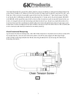
Chain Tension and Sharpening ..................................................................................................................................... 7
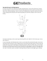
Sprocket Removal and Replacement ............................................................................................................................ 8
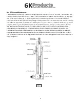
Bar Oil Pump Adjustment ............................................................................................................................................. 9
Operating Instruction ................................................................................................................................................. 10
Parts and Service Information .................................................................................................................................... 10
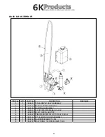
Main Sub Assembly Parts ........................................................................................................................................... 11
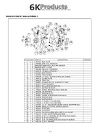
Simple Saw Assembly Parts ........................................................................................................................................ 12
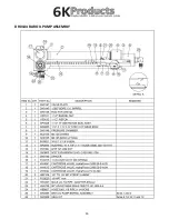
Bar Oil Pump Assembly Parts ..................................................................................................................................... 13
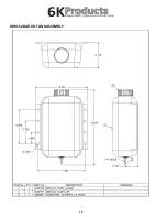
Bar Oil Tank Assembly Parts ....................................................................................................................................... 14
Summary of Contents for DH0626
Page 12: ...12 DH0641 SIMPLE SAW ASSEMBLY...


