7.
CONNECTOR PINOUT (REAR)
X1 Connector (Power and CAN)
Pin Number
Signal
Description
1
GND
Ground connection
2
+24V
Board power supply
3
CAN L
CAN-Bus Low signal
4
CAN H
CAN-Bus High signal
X1 pinout description
Plug type:
•
Manufacturer:
Weidmuller
•
Model:
BLZF 3.50/04/180
8.
LED BEHAVIOUR
LED Name
LED Behaviour
Definition of Behaviour
STATUS
Off
Board is not powered on or power supply is not reaching the
microcontroller.
Solid green
Board is powered on, but firmware of microcontroller is not present or
is not running due an error.
Blinking green
Board is powered on and firmware is running properly.
LED behaviour
9.
SWITCH CONFIGURATION
Switch
Name
Pin switch
Definition of Behaviour
SW1
1 & 2
Switches 1 and 2 set the CAN communication speed:
3 to 8
The logic address is composed by 2 elements: the module
identification and the hardware address. The module identification is
set on firmware and cannot be changed. The hardware address is
selected by switches 3 to 8, being 3 the least significant bit (LSB) and
8 the most significant bit (MSB):
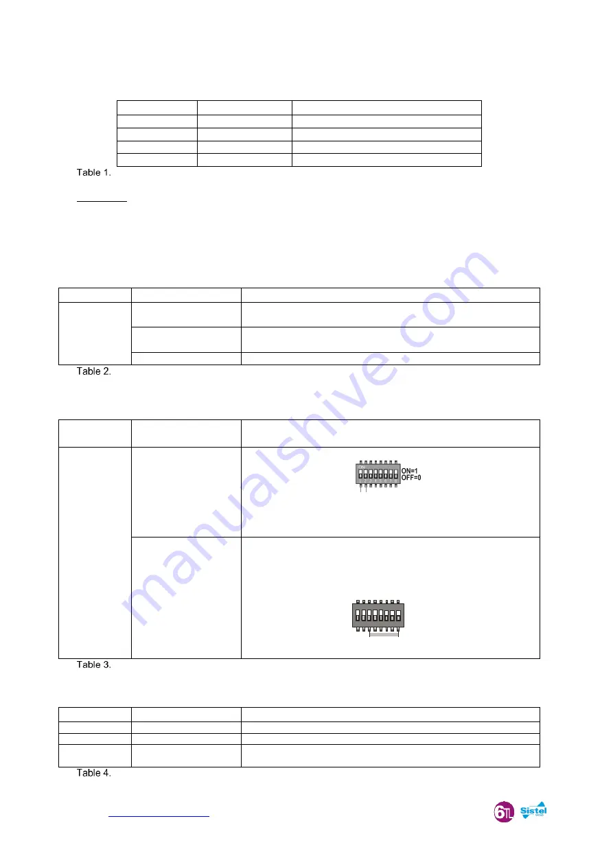
ON
1 2 3 4 5 6 7 8
ON=1
OFF=0
LSB
MSB
Board Address
SW1 behaviour
Switch ID
Description
Definition of Behaviour
SW2
BOOT0
Factory use.
Must be OPEN on operation.
SW3
RESET
Must be OPEN on operation. A temporary bridge causes a reset of the board.
SW4
CAN-END
Placing jumper adds a 120 Ohm resistor between the CAN-High and CAN-Low
signals of CAN-Bus.
Switches description
00 = 50 kbps
10 = 100 kbps
01 = 125 kbps
11 = 250 kbps


