A
DMINISTRATOR
S
ECTION
C
HAPTER
2: C
ONFIGURING
THE
ER S
ERVER
26
8
E
6 T
ECHNOLOGIES
, E
NTERPRISE
R
EPORTER
A
DMINISTRATOR
U
SER
G
UIDE
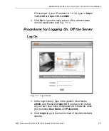
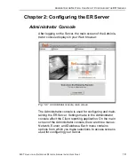
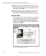
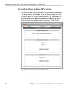
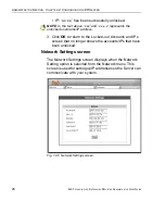
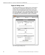
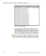
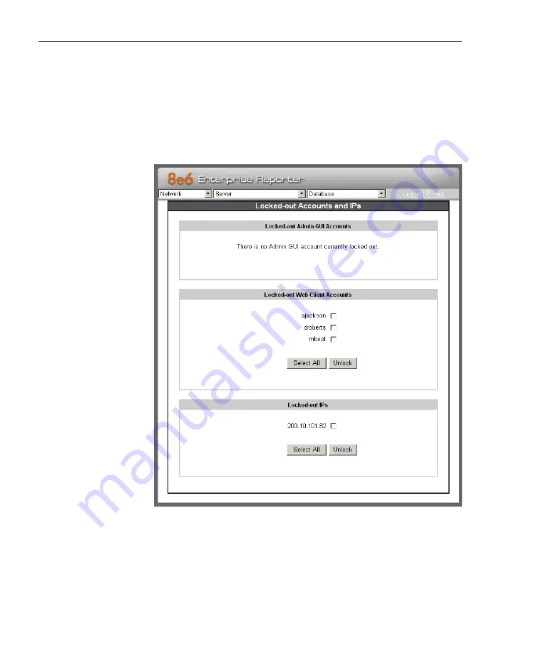
Locked-out Accounts and IPs screen
The Locked-out Accounts and IPs screen displays when the
Lockouts option is selected from the Network menu. This
screen is used for unlocking accounts or IP addresses of
administrators and sub-administrators that are currently
locked out of the Administrator console or Web Client.
Fig. 1:2-5 Locked-out Accounts and IPs screen


